Ford Fiesta: Fuel Tank and Lines - 1.6L EcoBoost (132kW/180PS) – Sigma / Fuel Tank. Removal and Installation
Ford Fiesta 2014 - 2019 Service Manual / Fuel System / Fuel Tank and Lines - 1.6L EcoBoost (132kW/180PS) – Sigma / Fuel Tank. Removal and Installation
Special Tool(s) / General Equipment
| Hose Clamp(s) | |
| Powertrain Jack |
Removal
NOTE: Removal steps in this procedure may contain installation steps.
-
With the vehicle in NEUTRAL, position it on a hoist.
Refer to: Jacking and Lifting - Overview (100-02 Jacking and Lifting, Description and Operation).
-
Release the fuel system pressure.
Refer to: Fuel System Pressure Release (310-00B Fuel System - General Information - 1.6L EcoBoost (132kW/180PS) – Sigma, General Procedures).
-
Drain the fuel tank.
Refer to: Fuel Tank Draining (310-00B Fuel System - General Information - 1.6L EcoBoost (132kW/180PS) – Sigma, General Procedures).
-
Remove the rear seat cushion.
Refer to: Rear Seat Cushion (501-10 Seating, Removal and Installation).
-
Remove the cover.
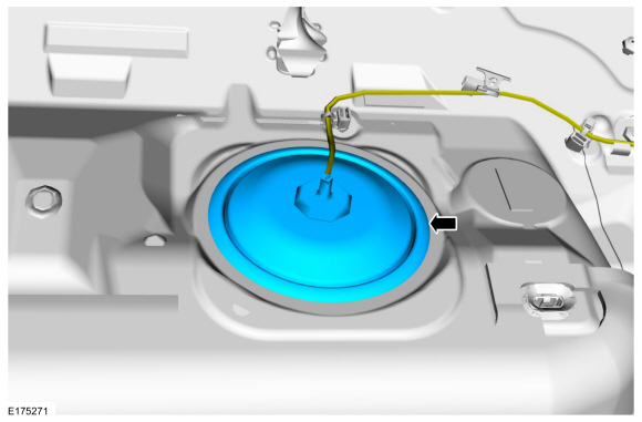 |
-
Disconnect the electrical connector and the fuel line quick release coupling.
Refer to: Quick Release Coupling (310-00B Fuel System - General Information - 1.6L EcoBoost (132kW/180PS) – Sigma, General Procedures).
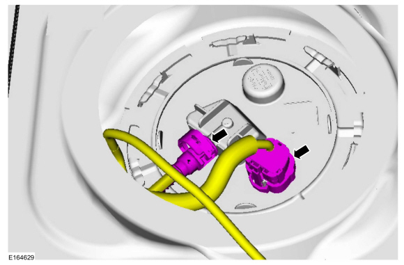 |
-
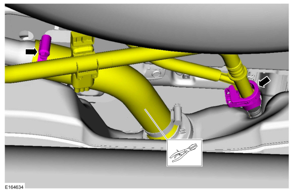
Disconnect the insulators and position aside the exhaust.
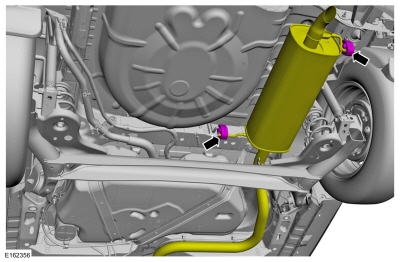 |
-
Remove the retainers and shield.
 |
-
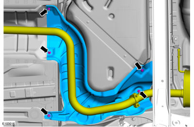
-
Clamp off the fuel filler pipe hose.
Use the General Equipment: Hose Clamp(s)
-
Release the clamp and position aside the filler pipe hose.
-
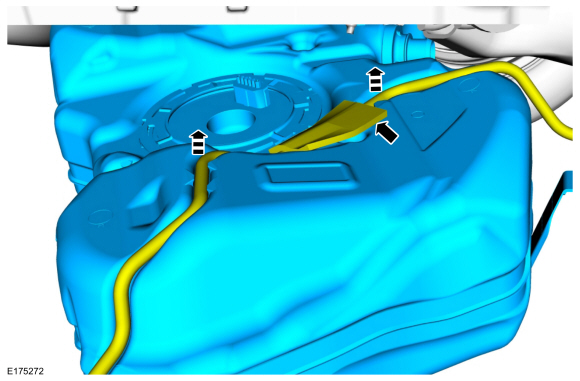
Disconnect vapor line quick release coupling and position aside.
Refer to: Quick Release Coupling (310-00B Fuel System - General Information - 1.6L EcoBoost (132kW/180PS) – Sigma, General Procedures).
-
Clamp off the fuel filler pipe hose.
 |
-
Remove and discard the fuel tank strap bolts.
Use the General Equipment: Powertrain Jack
Torque: 18 lb.ft (25 Nm)
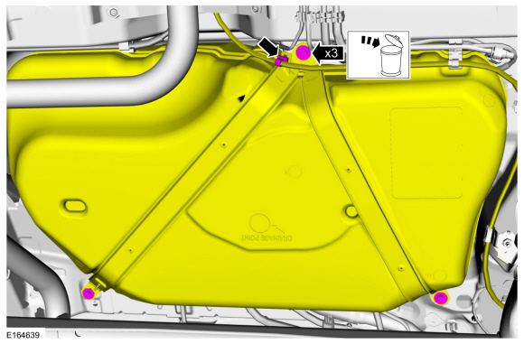 |
-
Lower the fuel tank far enough to disconnect the vapor line. Remove the fuel tank.
 |
Installation
-
To install, reverse the removal procedure.
 Fuel Tank and Lines - Overview. Description and Operation
Overview
Fuel Tank and Lines
The fuel tank and lines consist of the following:
single container fuel tank.
lifetime in tank fuel filter (serviced as part of the fuel pump)...
 Fuel Level Sender. Removal and Installation
Removal
NOTE:
Removal steps in this procedure may contain installation details.
Remove the Fuel Pump and Sender Unit.
Refer to: Fuel Pump and Sender Unit (310-01B Fuel Tank and Lines - 1...
Other information:
Ford Fiesta 2014 - 2019 Service Manual: Supplemental Restraint System (SRS) Depowering and Repowering. General Procedures
Depower NOTE: The SRS must be fully operational and free of faults before releasing the vehicle to the customer. Turn the ignition OFF. At the BCM , located behind the glove box, remove the BCM fuse 20 (10A). Refer to Wiring Cell 11 Fuse and Relay Information for schematic and connector information...
Ford Fiesta 2014 - 2019 Service Manual: Front Brake Flexible Hose. Removal and Installation
Removal NOTICE: If the fluid is spilled on the paintwork, the affected area must be immediately washed down with cold water. NOTICE: Make sure that all openings are sealed. NOTE: Removal steps in this procedure may contain installation details...
Categories
- Manuals Home
- Ford Fiesta Service Manual (2014 - 2019)
- Front Suspension
- Camshafts. Removal and Installation
- Engine System - General Information
- Manual Transmission - 6-Speed Manual Transmission – B6
- Clutch - 6-Speed Manual Transmission – B6
Rear Wheel Speed Sensor. Removal and Installation
Removal
NOTE: Removal steps in this procedure may contain installation details.
Remove the retainer and pull the rear splash shield outward.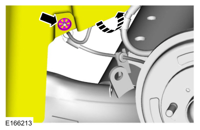 Disconnect the electrical connector and detach the wiring retainer.
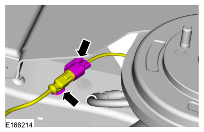
Copyright © 2026 www.fofiesta7.com