Ford Fiesta: Fuel Charging and Controls - 1.6L EcoBoost (132kW/180PS) – Sigma / Fuel Pump. Removal and Installation
Materials
| Name | Specification |
|---|---|
| Engine Oil - SAE 5W-20 - Synthetic Blend Motor Oil XO-5W20-Q1SP |
WSS-M2C945-B1 |
Removal
 WARNING:
Do not work on the fuel system until the pressure has been
released and the engine has cooled. Fuel in the high-pressure fuel
system is hot and under very high pressure. High-pressure fuel may cause
cuts and contact with hot fuel may cause burns. Failure to follow these
instructions may result in serious personal injury.
WARNING:
Clean all fuel residue from the engine compartment. If not
removed, fuel residue may ignite when the engine is returned to
operation. Failure to follow this instruction may result in serious
personal injury.
WARNING:
Always disconnect the battery ground cable at the battery
when working on an evaporative emission (EVAP) system or fuel-related
component. Highly flammable mixtures are always present and may be
ignited. Failure to follow these instructions may result in serious
personal injury.
NOTICE: Do not loosen any fittings or plugs on the fuel injection pump.
-
Release the fuel system pressure.
Refer to: Fuel System Pressure Release (310-00B Fuel System - General Information - 1.6L EcoBoost (132kW/180PS) – Sigma, General Procedures).
-
Disconnect the battery.
Refer to: Battery Disconnect and Connect (414-01 Battery, Mounting and Cables, General Procedures).
-
Remove the ignition coil-on-plugs.
Refer to: Ignition Coil-On-Plug (303-07B Engine Ignition - 1.6L EcoBoost (132kW/180PS) – Sigma, Removal and Installation).
-
Remove the air cleaner outlet pipe.
Refer to: Air Cleaner Outlet Pipe (303-12B Intake Air Distribution and Filtering - 1.6L EcoBoost (132kW/180PS) – Sigma, Removal and Installation).
-
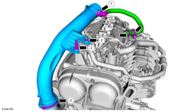
-
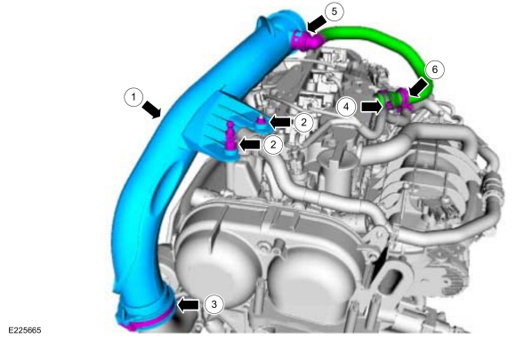
Disconnect the crankcase ventilation tube quick
release coupling. Release the hose retainer, release the clamp and then
remove the crankcase ventilation tube.
Refer to: Quick Release Coupling (310-00B Fuel System - General Information - 1.6L EcoBoost (132kW/180PS) – Sigma, General Procedures).
-
Remove the TC air inlet pipe nut, the ball stud and loosen the TC air inlet pipe clamp, then remove the TC inlet pipe.
-
Disconnect the crankcase ventilation tube quick
release coupling. Release the hose retainer, release the clamp and then
remove the crankcase ventilation tube.
 |
-
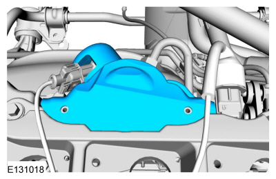
NOTE: When removing or installing the fuel injection pump noise insulator, spreading the openings will reduce the risk of damage.
Remove the high-pressure fuel pump noise insulator.
 |
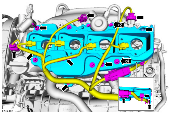
-
-
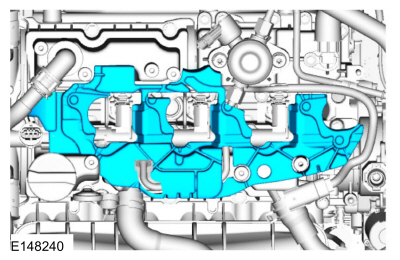
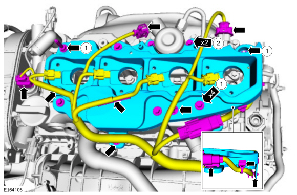
Release the wiring harness retainers. Disconnect the FRP sensor
electrical connector, the fuel injection pump electrical connector and
the CMP electrical connector. Position the wiring harness aside.
-
Remove the ignition coil-on-plug mounting bracket
retaining nut. Loosen the captured remaining ignition coil-on-plug
mounting bracket retainers and then remove the ignition coil-on-plug
mounting bracket.
-
Release the wiring harness retainers. Disconnect the FRP sensor
electrical connector, the fuel injection pump electrical connector and
the CMP electrical connector. Position the wiring harness aside.
 |
-
Remove the ignition coil-on-plug mounting bracket insulator.
 |
-
-
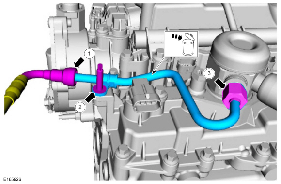
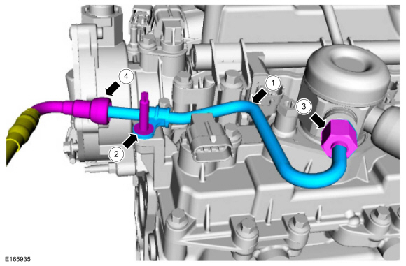
Disconnect the high-pressure fuel pump fuel supply tube.
Refer to: Spring Lock Couplings (310-00B Fuel System - General Information - 1.6L EcoBoost (132kW/180PS) – Sigma, General Procedures).
-
Remove the high-pressure fuel pump fuel supply tube studbolt.
-
Disconnect the high-pressure fuel pump fuel supply
tube flare nut. Remove and discard the high-pressure fuel pump fuel
supply tube.
-
Disconnect the high-pressure fuel pump fuel supply tube.
 |
-
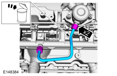
NOTICE: To release the fuel pressure in the high-pressure fuel tube, wrap the high-pressure fuel pump flare nut with a shop towel to absorb any residual fuel pressure during the loosening of high-pressure fuel pump flare nut.
Disconnect the high-pressure fuel tube flare nuts. Remove and discard the high-pressure fuel tube.
 |
-
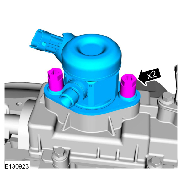
NOTE: Alternately loosen the 2 fuel injection pump bolts one complete revolution at a time.
Remove the high-pressure fuel pump bolts and then remove the high-pressure fuel pump.
 |
-
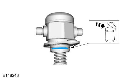
Remove and discard the high-pressure fuel pump O-ring seal.
 |
-
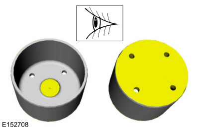
Remove the high-pressure fuel pump drive tappet.
 |
-
Inspect the high-pressure fuel pump tappet. If any flat
spots or scoring are found, especially in the indicated areas, then
inspect the high-pressure fuel pump and the high-pressure fuel pump
tappet drive lobe. Install new components as needed.
 |
Installation
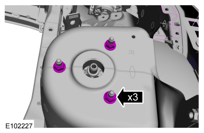
-
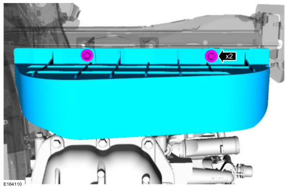
Remove the retainers and the cover.
 |
-
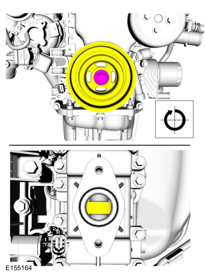
NOTICE: Only rotate the crankshaft Clockwise (CW) or damage to the engine may occur.
NOTE: The cam lobe for the fuel high-pressure pump must be at BDC for the fuel high-pressure pump installation.
Rotate the camshaft as needed until the cam lobe for the high-pressure fuel pump is at BDC .
 |
-
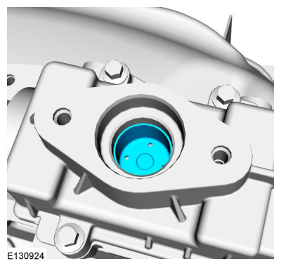
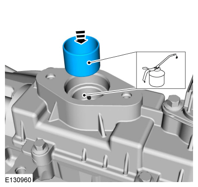
Lubricate the high-pressure fuel pump tappet and the
high-pressure fuel pump drive unit bore with clean engine oil.
Material: Engine Oil - SAE 5W-20 - Synthetic Blend Motor Oil / XO-5W20-Q1SP (WSS-M2C945-B1)
 |
-
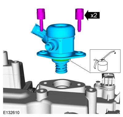
NOTE: Install a new high-pressure fuel pump O-ring seal.
Install the high-pressure fuel pump and loosely install the high-pressure fuel pump bolts, alternately tighten each bolt one half of a revolution until seated. Tighten the high-pressure fuel pump bolts.
Torque: 115 lb.in (13 Nm)
 |
-
Install the cover, then install and tighten the cover retainers.
Torque: 27 lb.in (3 Nm)
|
-
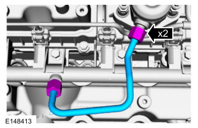
NOTE: Only tighten the 2 high-pressure fuel tube flare nuts finger tight at this stage.
NOTE: Make sure that a new component is installed.
NOTE: Calculate the correct torque wrench setting for the following torque using the Torque Wrench Adapter Formulas.
Tighten the high-pressure fuel tube flare nuts in the following 3 stages.
Torque:
Stage 1: 15 lb.ft (21 Nm)
Stage 2: Wait 5min
Stage 3: 15 lb.ft (21 Nm)
 |
-
-
NOTE: Make sure that a new component is installed.
Install the new high-pressure fuel pump fuel supply tube and the high-pressure fuel pump fuel supply tube studbolt finger tight.
-
Tighten install the high-pressure fuel pump fuel supply tube studbolt.
Torque: 62 lb.in (7 Nm)
-
NOTE: Calculate the correct torque wrench setting for the following torque. Refer to the Torque Wrench Adapter Formulas.
Tighten the high-pressure fuel pump fuel supply tube flare nut in the following 3 stages.
Torque:
Stage 1: 15 lb.ft (21 Nm)
Stage 2: Wait 5min
Stage 3: 15 lb.ft (21 Nm)
-
Connect the high-pressure fuel pump fuel supply tube.
Refer to: Spring Lock Couplings (310-00B Fuel System - General Information - 1.6L EcoBoost (132kW/180PS) – Sigma, General Procedures).
-
 |
-
Install the ignition coil-on-plug mounting bracket insulator.
|
-
-
Install the ignition coil-on-plug mounting bracket,
then install and tighten the ignition coil-on-plug mounting bracket
retainers.
Torque:
Stage 1: 89 lb.in (10 Nm)
Stage 2: 53 lb.in (6 Nm)
-
Install the wiring harness, then attach the wiring harness retainers.
Connect the FRP sensor electrical connector, the fuel injection pump
electrical connector and the CMP electrical connector.
-
Install the ignition coil-on-plug mounting bracket,
then install and tighten the ignition coil-on-plug mounting bracket
retainers.
 |
-
NOTE: When removing or installing the fuel injection pump noise insulator, spreading the openings will reduce the risk of damage.
Install the high-pressure fuel pump noise insulator.
|
-
-
Install the TC inlet pipe.
-
Install and tighten the TC inlet pipe ball stud and retaining nut.
Torque: 44 lb.in (5 Nm)
-
Tighten the TC inlet tube clamp.
Torque: 44 lb.in (5 Nm)
-
Install the crankcase ventilation tube and clamp.
-
Connect the crankcase ventilation tube quick release coupling.
Refer to: Quick Release Coupling (310-00B Fuel System - General Information - 1.6L EcoBoost (132kW/180PS) – Sigma, General Procedures).
-
Attach the hose retainer.
Torque: 44 lb.in (5 Nm)
-
Install the TC inlet pipe.
 |
-
Install the air cleaner outlet pipe.
Refer to: Air Cleaner Outlet Pipe (303-12B Intake Air Distribution and Filtering - 1.6L EcoBoost (132kW/180PS) – Sigma, Removal and Installation).
-
Install the ignition coil-on-plugs.
Refer to: Ignition Coil-On-Plug (303-07B Engine Ignition - 1.6L EcoBoost (132kW/180PS) – Sigma, Removal and Installation).
-
Connect the battery.
Refer to: Battery Disconnect and Connect (414-01 Battery, Mounting and Cables, General Procedures).
-
Pressurize the fuel system.
Refer to: Fuel System Pressure Release (310-00B Fuel System - General Information - 1.6L EcoBoost (132kW/180PS) – Sigma, General Procedures).
 Fuel Injectors. Removal and Installation
Removal and Installation
Refer to: Fuel Rail (303-04B Fuel Charging and Controls - 1.6L EcoBoost (132kW/180PS) – Sigma, Removal and Installation)...
 Fuel Pump Driver Module (FPDM). Removal and Installation
Removal
NOTE:
The FPDM is
located under the carpet and under left front seat attached to the rear
of the front cross floor support in front of the left front seat...
Other information:
Ford Fiesta 2014 - 2019 Service Manual: Evaporative Emission Canister Vent Solenoid. Removal and Installation
Removal NOTE: Removal steps in this procedure may contain installation details. Remove the EVAP canister. Refer to: Evaporative Emission Canister (303-13B Evaporative Emissions - 1.6L EcoBoost (132kW/180PS) – Sigma, Removal and Installation)...
Ford Fiesta 2014 - 2019 Service Manual: Pinpoint Test - DTC: B. Diagnosis and Testing
B0002:11, B0002:12, B0002:13 and B0002:1A Refer to Wiring Diagrams Cell 46 for schematic and connector information. Normal Operation and Fault Conditions The RCM continuously monitors the driver airbag stage 2 circuits for the following faults: Resistance out of range Unexpected voltage Short to ground Faulted driver airbag If a f..
Categories
- Manuals Home
- Ford Fiesta Service Manual (2014 - 2019)
- Front Strut and Spring Assembly. Removal and Installation
- Cylinder Head. Removal and Installation
- Maintenance Schedules
- Service Information
- Lower Arm. Removal and Installation
Front Strut and Spring Assembly. Removal and Installation
Removal
NOTE: Removal steps in this procedure may contain installation details.
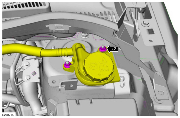
NOTE: This step is only necessary when installing a new component to the left-hand side.
Remove the nuts and position aside the remote brake fluid reservoir.Torque: 62 lb.in (7 Nm)
 Remove the strut and spring assembly upper mount nuts.
 Torque: 22 lb.ft (30 Nm)