Ford Fiesta: Front Suspension / Front Strut and Spring Assembly. Removal and Installation
Ford Fiesta 2014 - 2019 Service Manual / Suspension / Front Suspension / Front Strut and Spring Assembly. Removal and Installation
Removal
NOTE: Removal steps in this procedure may contain installation details.
NOTE: This step is only necessary when installing a new component to the left-hand side.
-
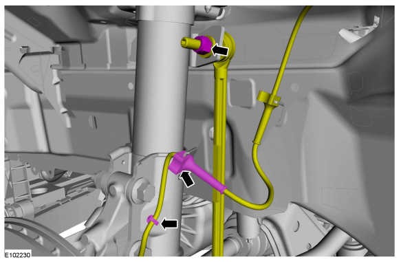
Remove the nuts and position aside the remote brake fluid reservoir.
Torque: 62 lb.in (7 Nm)
 |
-
Remove the strut and spring assembly upper mount nuts.
Torque: 22 lb.ft (30 Nm)
 |
-
Remove the wheel and tire.
Refer to: Wheel and Tire (204-04A Wheels and Tires, Removal and Installation).
-
-
Detach the retainer and disconnect the wheel speed
sensor harness from the strut and spring assembly bracket.
-
Remove the stabilizer bar link upper nut and detach the link from the strut.
Torque: 35 lb.ft (48 Nm)
-
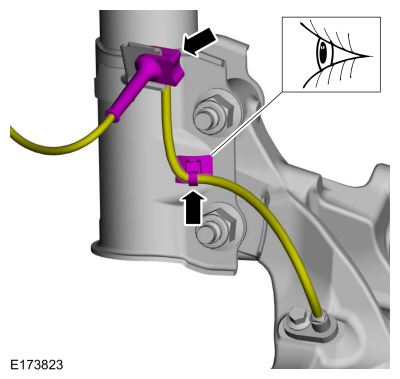
Detach the retainer and disconnect the wheel speed
sensor harness from the strut and spring assembly bracket.
 |
-
Remove the brake flexible hose bracket bolt and disconnect the hose from the strut and spring assembly.
Torque: 19 lb.ft (26 Nm)
 |
-
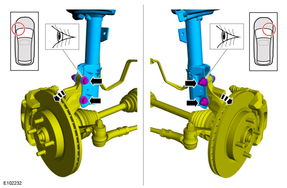
Remove the wheel knuckle-to-strut nuts, bolts and the strut and spring assembly.
Torque:
Stage 1: 60 lb.ft (82 Nm)
Stage 2: 90°
 |
Installation
-
To install, reverse the removal procedure.
-
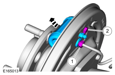
NOTE: Always install a new clip on the new strut due to different design.
Install the clip and connect the wheel speed sensor harness.
 |
-
Check and if necessary align the front end.
Refer to: Front Toe Adjustment (204-00 Suspension System - General Information, General Procedures).
 Front Stabilizer Bar Bushing. Removal and Installation
Removal
NOTE:
Removal steps in this procedure may contain installation details.
With the vehicle in NEUTRAL, position it on a hoist...
 Front Stabilizer Bar. Removal and Installation
Special Tool(s) /
General Equipment
300-OTC1585AEPowertrain Lift
Tie Rod End Remover
Wooden Block
Removal
WARNING:
Before beginning any service procedure in this section,
refer to Safety Warnings in section 100-00 General Information...
Other information:
Ford Fiesta 2014 - 2019 Service Manual: Wheel Studs - 1.6L EcoBoost (132kW/180PS) – Sigma. Removal and Installation
Special Tool(s) / General Equipment 211-001 (TOOL-3290-D) Remover, Tie-Rod End Removal NOTICE: Suspension fasteners are critical parts that affect performance of vital components and systems. Failure of these fasteners may result in major service expense...
Ford Fiesta 2014 - 2019 Service Manual: Power Steering - System Operation and Component Description. Description and Operation
System Operation System Diagram Item Description 1 EPAS column 2 HS-CAN 3 EPAS motor 4 Steering shaft position sensor 5 Steering shaft torque sensor 6 PSCM 7 IPC 8 ABS module 9 PCM Network Message Chart ..
Categories
- Manuals Home
- Ford Fiesta Service Manual (2014 - 2019)
- Valve Cover. Removal and Installation
- Front Strut and Spring Assembly. Removal and Installation
- Camshafts. Removal and Installation
- Service Information
- Lower Arm. Removal and Installation
Brake Backing Plate. Removal and Installation
Removal
NOTE: Removal steps in this procedure may contain installation details.
Remove the brake shoes.Refer to: Brake Shoes (206-02 Drum Brake, Removal and Installation).
Disconnect the brake tube fitting.
Torque: 159 lb.in (18 Nm) Remove the bolt and wheel cylinder.
Torque: 106 lb.in (12 Nm)
 Disconnect the brake shoe lever fitting and re
Copyright © 2026 www.fofiesta7.com