Ford Fiesta: Electronic Engine Controls - 1.6L EcoBoost (132kW/180PS) – Sigma / Rear Knock Sensor (KS). Removal and Installation
Ford Fiesta 2014 - 2019 Service Manual / Engine / Electronic Engine Controls - 1.6L EcoBoost (132kW/180PS) – Sigma / Rear Knock Sensor (KS). Removal and Installation
Removal
NOTE: Removal steps in this procedure may contain installation details.
-
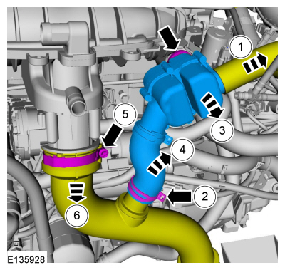
Release the hose clamp and disconnect the hose from the crankcase vent oil separator.
 |
-
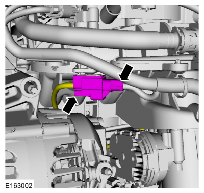
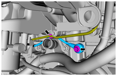
Disconnect the KS electrical connector.
 |
-
NOTE: Note the position of the component before removal. The KS must be installed in the 10 o'clock position.
Remove the bolt and the KS .
Torque: 159 lb.in (18 Nm)
 |
Installation
-
NOTE: Make sure that the components are installed to the position noted before removal.
To install, reverse the removal procedure.
 Front Knock Sensor (KS). Removal and Installation
Removal
NOTE:
Removal steps in this procedure may contain installation details.
Remove the throttle body.
Refer to: Throttle Body (303-04B Fuel Charging and Controls - 1...
 Variable Camshaft Timing (VCT) Oil Control Solenoid. Removal and Installation
Materials
Name
Specification
Engine Oil - SAE 5W-20 - Synthetic Blend Motor OilXO-5W20-Q1SP
WSS-M2C945-B1
Removal
Remove the engine appearance cover...
Other information:
Ford Fiesta 2014 - 2019 Service Manual: Engine. Installation
Special Tool(s) / General Equipment 205-461Protector, Differential Oil Seal (pair)TKIT-2000AP-FLM/LMTKIT-2002-F/FM 300-OTC1585AEPowertrain Lift 300-OTC1819E2,200# Floor Crane, Fold Away 303-1502Lifting Device EngineTKIT-2012A-FLTKIT-2012A-ROW 303-476 (T94P-9472-A) Socket, Exhaust Gas Oxygen SensorTKIT-1994-LM/MTKIT-1994-FTKIT-1994-FLM/FM ..
Ford Fiesta 2014 - 2019 Service Manual: Autolamps. Diagnosis and Testing
Diagnostics in this manual assume a certain skill level and knowledge of Ford-specific diagnostic practices. REFER to: Diagnostic Methods (100-00 General Information, Description and Operation). DTC Chart: BCM BCM DTC Chart DTC Description Action B1A85:21 Ambient Li..
Categories
- Manuals Home
- Ford Fiesta Service Manual (2014 - 2019)
- Engine - 1.6L EcoBoost (132kW/180PS) – Sigma
- Maintenance Schedules
- Front Suspension
- Timing Belt. Removal and Installation
- Manual Transmission - 6-Speed Manual Transmission – B6
Brake Backing Plate. Removal and Installation
Removal
NOTE: Removal steps in this procedure may contain installation details.
Remove the brake shoes.Refer to: Brake Shoes (206-02 Drum Brake, Removal and Installation).
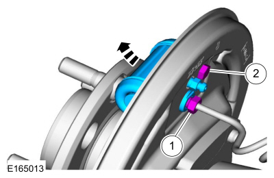
Disconnect the brake tube fitting.
Torque: 159 lb.in (18 Nm) Remove the bolt and wheel cylinder.
Torque: 106 lb.in (12 Nm)
 Disconnect the brake shoe lever fitting and re
Copyright © 2026 www.fofiesta7.com