Ford Fiesta: Electronic Engine Controls - 1.6L EcoBoost (132kW/180PS) – Sigma / Front Knock Sensor (KS). Removal and Installation
Ford Fiesta 2014 - 2019 Service Manual / Engine / Electronic Engine Controls - 1.6L EcoBoost (132kW/180PS) – Sigma / Front Knock Sensor (KS). Removal and Installation
Removal
NOTE: Removal steps in this procedure may contain installation details.
-
Remove the throttle body.
Refer to: Throttle Body (303-04B Fuel Charging and Controls - 1.6L EcoBoost (132kW/180PS) – Sigma, Removal and Installation).
-
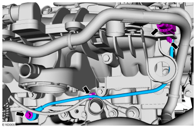
NOTE: Note the position of the component before removal. The KS must be installed in the 2 o'clock position.
-
Disconnect the KS electrical connector.
-
Remove the bolt and the KS .
Torque: 159 lb.in (18 Nm)
-
Disconnect the KS electrical connector.
 |
Installation
-
NOTE: Make sure that the components are installed to the position noted before removal.
To install, reverse the removal procedure.
 Powertrain Control Module (PCM). Removal and Installation
Removal
NOTE:
Removal steps in this procedure may contain installation details.
NOTE:
This step is only necessary when installing a new component...
 Rear Knock Sensor (KS). Removal and Installation
Removal
NOTE:
Removal steps in this procedure may contain installation details.
Release the hose clamp and disconnect the hose from the crankcase vent oil separator...
Other information:
Ford Fiesta 2014 - 2019 Service Manual: Tire Pressure Monitoring System (TPMS) - Overview. Description and Operation
Overview The BCM monitors the tire pressure in the 4 road tires with tire pressure sensors that communicate the tire pressure via radio signals to the BCM . The tire pressure sensors are battery operated and mounted to the valve stems. All of the controlling software for the TPMS is contained in the BCM ...
Ford Fiesta 2014 - 2019 Service Manual: Steering Column Shaft. Removal and Installation
Special Tool(s) / General Equipment Steering Wheel Holder Removal NOTE: The removal steps in this procedure may include installation details. NOTICE: Do not allow the steering column to rotate while the steering column shaft is disconnected or damage to the steering column internal sensor may result...
Categories
- Manuals Home
- Ford Fiesta Service Manual (2014 - 2019)
- Valve Cover. Removal and Installation
- Service Information
- Camshafts. Removal and Installation
- Engine Component View. Description and Operation
- Manual Transmission, Clutch, Transfer Case and Power Transfer Unit
Front Strut and Spring Assembly. Removal and Installation
Removal
NOTE: Removal steps in this procedure may contain installation details.
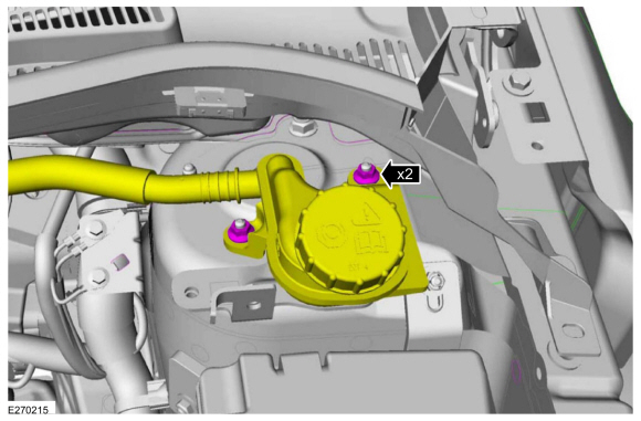
NOTE: This step is only necessary when installing a new component to the left-hand side.
Remove the nuts and position aside the remote brake fluid reservoir.Torque: 62 lb.in (7 Nm)
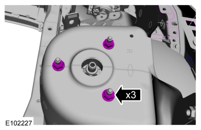
 Remove the strut and spring assembly upper mount nuts.
 Torque: 22 lb.ft (30 Nm)
Copyright © 2026 www.fofiesta7.com