Ford Fiesta: Drum Brake / Brake Backing Plate. Removal and Installation
Ford Fiesta 2014 - 2019 Service Manual / Brake System / Drum Brake / Brake Backing Plate. Removal and Installation
Removal
NOTE: Removal steps in this procedure may contain installation details.
-
Remove the brake shoes.
Refer to: Brake Shoes (206-02 Drum Brake, Removal and Installation).
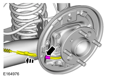
-
-
Disconnect the brake tube fitting.
Torque: 159 lb.in (18 Nm)
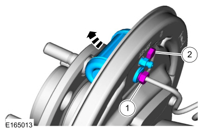
-
Remove the bolt and wheel cylinder.
Torque: 106 lb.in (12 Nm)
-
Disconnect the brake tube fitting.
 |
-
Disconnect the brake shoe lever fitting and remove the brake shoe lever.
 |
-
Remove the bolts, the wheel hub and bearing and the brake backing plate.
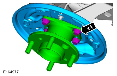 |
Installation
-
To install, reverse the removal procedure.
-
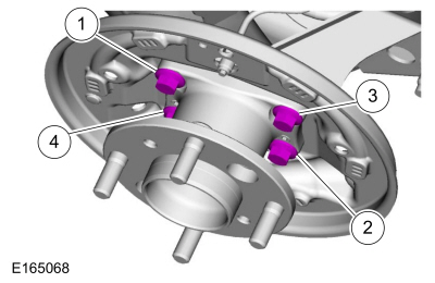
Install the brake backing plate, the wheel hub and bearing and the bolts.
Torque: 48 lb.ft (65 Nm)
|
-
-
Tighten the bolt in two stages.
Torque:
Stage 1: Loosen: 90°
Stage 2: 48 lb.ft (65 Nm)
-
Tighten the bolt in two stages.
Torque:
Stage 1: Loosen: 90°
Stage 2: 48 lb.ft (65 Nm)
-
Tighten the bolt in two stages.
Torque:
Stage 1: Loosen: 90°
Stage 2: 48 lb.ft (65 Nm)
-
Tighten the bolt in two stages.
Torque:
Stage 1: Loosen: 90°
Stage 2: 48 lb.ft (65 Nm)
-
Tighten the bolt in two stages.
 |
-
Bleed the brake system.
Refer to: Brake System Pressure Bleeding (206-00 Brake System - General Information, General Procedures).
 Brake Drum. Removal and Installation
Removal
NOTE:
Removal steps in this procedure may contain installation details.
WARNING:
Before beginning any service procedure in this
manual, refer to health and safety warnings in section 100-00 General
Information...
 Brake Shoes. Removal and Installation
Special Tool(s) /
General Equipment
Flat Headed Screw Driver
Materials
Name
Specification
Motorcraft® Silicone Brake Caliper Grease and Dielectric CompoundXG-3-A
ESA-M1C200-AESE-M1C171-A
Removal
NOTE:
Removal steps in this procedure may contain installation details...
Other information:
Ford Fiesta 2014 - 2019 Service Manual: Timing Belt. Removal and Installation
Special Tool(s) / General Equipment 303-1097Locking Tool, Variable Camshaft Timing Oil Control UnitTKIT-2010B-FLMTKIT-2010B-ROW 303-1550Alignment Tool, Crankshaft Vibration DamperTKIT-2012A-FLTKIT-2012A-ROW 303-393-02Adapter for 303-393TKIT-2012A-FLTKIT-2012A-ROW 303-393ALocking Tool, FlywheelTKIT-2012A-FLTKIT-2012A-ROW 303-748Locking Tool, C..
Ford Fiesta 2014 - 2019 Service Manual: Occupant Classification System (OCS) Sensor. Removal and Installation
Special Tool(s) / General Equipment Hog Ring Plier Removal WARNING: The following procedure prescribes critical repair steps required for correct restraint system operation during a crash. Follow all notes and steps carefully. Failure to follow step instructions may result in incorrect operation of the restraint system and increases the risk of serious pe..
Categories
- Manuals Home
- Ford Fiesta Service Manual (2014 - 2019)
- Clutch - 6-Speed Manual Transmission – B6
- Cylinder Head. Removal and Installation
- Front Strut and Spring Assembly. Removal and Installation
- Camshafts. Removal and Installation
- Fuel Pump. Removal and Installation
Brake Drum. Removal and Installation
Removal
NOTE: Removal steps in this procedure may contain installation details.
 WARNING:
Before beginning any service procedure in this
manual, refer to health and safety warnings in section 100-00 General
Information. Failure to follow this instruction may result in serious
personal injury.
WARNING:
Before beginning any service procedure in this
manual, refer to health and safety warnings in section 100-00 General
Information. Failure to follow this instruction may result in serious
personal injury.
Remove the wheel and tire.
Refer to: Wheel and Tire (204-04A Wheels and Tires, Removal and Installation).
Copyright © 2026 www.fofiesta7.com