Ford Fiesta: Instrumentation, Message Center and Warning Chimes / Instrument Panel Cluster (IPC) - Overview. Description and Operation
Overview

| Item | Description |
|---|---|
| 1 | Left turn signal indicator |
| 2 | Door ajar indicator |
| 3 | Grade assist indicator |
| 4 | TPMS warning indicator |
| 5 | Tachometer |
| 6 | Powertrain malfunction (wrench)/service warning indicator |
| 7 | ABS warning indicator |
| 8 | Integrated LCD |
| 9 | Charging system warning indicator |
| 10 | Brake warning indicator |
| 11 | Airbag warning indicator |
| 12 | Low fuel warning indicator |
| 13 | Stability-traction control (sliding car icon) indicator |
| 14 | Speedometer |
| 15 | Right turn signal indicator |
| 16 | Cruise control indicator |
| 17 | Safety belt warning indicator |
| 18 | Stability-traction control disabled (sliding car OFF icon) indicator |
| 19 | Lights on indicator |
| 20 | Fuel gauge |
| 21 | High beam indicator |
| 22 | MIL |
| 23 | Low oil pressure warning indicator |
| 24 | Front fog lamp indicator |
| 25 | Engine temperature warning indicator |
The IPC contains gauges, informational indicators, warning indicators and an integrated LCD designed to provide the driver with system status and to alert the driver when certain conditions exist in the vehicle.
Gauges
Gauges inform the driver of the status of systems. The systems that use gauges are as follows:
- Engine rpm
- Fuel level
- Vehicle speed
Informational and Warning Indicators
Informational indicators provide information to the driver of conditions that exist in the vehicle. Warning indicators provide information to the driver of conditions that could potentially cause personal injury or alter vehicle performance.
All informational and warning indicators are Light Emitting Diodes (LEDs) and are not replaced separate from the IPC .
IPC Integrated LCD
The IPC integrated LCD , located in the top center of the IPC , uses a 3-line LCD . The IPC integrated LCD is controlled by the trip computer switch, located on the multifunction switch. The IPC integrated LCD provides the following information:
- Odometer
-
Trip odometer
- DTE
- average fuel economy
- average speed
- instantaneous fuel economy
- outside air temperature
- Engine temperature gauge
- PRNDL (automatic transmission only)
Network Messaged Inputs
Module messaging has increased over time and has become the standard for sending and receiving information required to operate the IPC . The majority of the inputs required to operate the IPC are received over the CAN .
Hardwired Inputs
The IPC requires hardwired inputs from components that are not on the CAN . These components are required for specific IPC functions.
The hardwired inputs are provided by the following components:
- Fuel sender
- Clutch switch
- Parking brake position switch
- A/C switch (vehicles equipped with EMTC )
- Accelerator pedal
- Brake fluid level switch
- Ambient Air Temperature (AAT) sensor
- Park detect switch (part of the floor shifter assembly, vehicles equipped with automatic transmission)
- Cruise control switches
- Brake pedal switch

 Instrument Panel Cluster (IPC) - System Operation and Component Description. Description and Operation
System Operation
System Diagram - Gauges
Item
Description
1
Fuel pump assembly
2
ABS
3
HS-CAN
4
IPC
5
PCM
6
HS-CAN
Network Message Chart - Gauges
Module Network Input Messages - IPC
Broadcast M..
Other information:
Ford Fiesta 2014 - 2019 Service Manual: Airbag and Seatbelt Pretensioner Supplemental Restraint System (SRS) - System Operation and Component Description. Description and Operation
System Operation System Diagram - Supplemental Restraint System (SRS) Item Description 1 RCM 2 HS-CAN 3 Passenger Front Door Impact Severity Sensor 4 Driver Safety Belt Buckle Sensor 5 RF Passenger Safety Belt Buckle Sensor 6 RH Front Impact Severity Sensor 7 Driver Front Door Impact Severity Sen..
Ford Fiesta 2014 - 2019 Service Manual: Lower Arm. Removal and Installation
Removal NOTICE: Suspension fasteners are critical parts that affect performance of vital components and systems. Failure of these fasteners may result in major service expense. Use the same or equivalent parts if replacement is necessary. Do not use a replacement part of lesser quality or substitute design. Tighten fasteners as specified. Remove the wheel and tire. R..
Categories
- Manuals Home
- Ford Fiesta Service Manual (2014 - 2019)
- Engine. Assembly
- Manual Transmission - 6-Speed Manual Transmission – B6
- Engine System - General Information
- Lower Arm. Removal and Installation
- Engine - 1.6L EcoBoost (132kW/180PS) – Sigma
Front Strut and Spring Assembly. Removal and Installation
Removal
NOTE: Removal steps in this procedure may contain installation details.
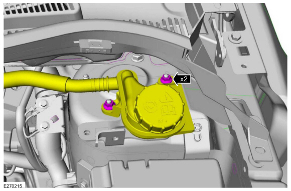
NOTE: This step is only necessary when installing a new component to the left-hand side.
Remove the nuts and position aside the remote brake fluid reservoir.Torque: 62 lb.in (7 Nm)
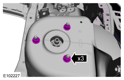
 Remove the strut and spring assembly upper mount nuts.
 Torque: 22 lb.ft (30 Nm)