Ford Fiesta: Manual Transmission - 6-Speed Manual Transmission – B6 / Output Shaft. Disassembly and Assembly of Subassemblies
Special Tool(s) / General Equipment
 |
205-199
(T83T-3132-A1)
Installer, Spindle/Axle Shaft T83-4000-A TKIT-1983-F TKIT-1983-FLM TKIT-1983-FX |
 |
205-D015
(D80L-630-4)
Step Plate |
 |
211-014 Remover, Steering Wheel |
| Hydraulic Press | |
| Hot Air Gun | |
| Bearing Separator | |
| Vise | |
| Vise Jaw Protectors | |
Materials
| Name | Specification |
|---|---|
| Motorcraft® Dual Clutch Transmission Fluid XT-11-QDC |
WSS-M2C200-D2 |
DISASSEMBLY
NOTE: If the front bearing needs to be replaced, replace the output shaft.
-
NOTICE: Use vise jaw protectors or damage to the output shaft can occur.
Install the output shaft in a vise. Clamp the output shaft on the flat surfaces.
Use the General Equipment: Vise
Use the General Equipment: Vise Jaw Protectors
 |
-
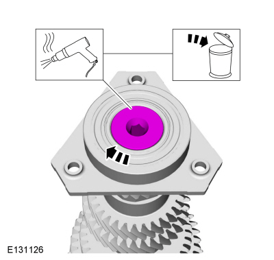
NOTE: The component has a left-hand thread.
Heat the bolt to melt the Loctite® and remove and discard the rear bearing bolt.
Use the General Equipment: Hot Air Gun
 |
-
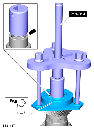
Using the special tools, remove the output shaft rear bearing.
Use Special Service Tool: 211-014 Remover, Steering Wheel.
 |
-
NOTE: Only tighten the bolts on the bearing separator finger tight.
Remove 6th gear.
Use Special Service Tool: 205-D015 (D80L-630-4) Step Plate.
Use the General Equipment: Hydraulic Press
Use the General Equipment: Bearing Separator
 |
-
NOTE: Only tighten the bolts on the bearing separator finger tight.
Remove 5th and 4th gear.
Use the General Equipment: Bearing Separator
Use the General Equipment: Hydraulic Press
 |
-
-
Push the 1st-2nd gear synchronizer sleeve down to the 1st gear position.
-
Remove 2nd and 3rd gear.
Use the General Equipment: Bearing Separator
Use the General Equipment: Hydraulic Press
-
Push the 1st-2nd gear synchronizer sleeve down to the 1st gear position.
 |
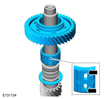
-
Remove the 2nd gear synchronizer assembly.
 |
-
NOTE: Note the position of the components before removal.
-
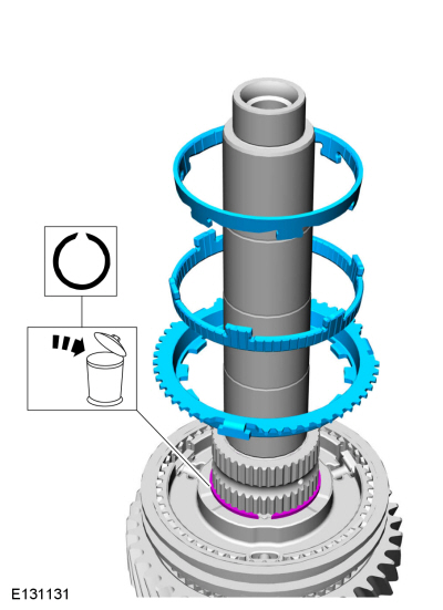
Remove the 1st-2nd gear synchronizer sleeve.
-
Remove the detents.
-
Remove the 1st-2nd gear synchronizer sleeve.
 |
-
Remove the 1st-2nd gear synchronizer hub.
Use the General Equipment: Hydraulic Press
 |
-
Remove 1st gear, release the roller bearing retainer and remove the roller bearing. Remove the thrust washer.
 |
ASSEMBLY
-
Install the thrust washer. Install the roller bearing and connect the roller bearing cage. Install 1st gear.
Material: Motorcraft® Dual Clutch Transmission Fluid / XT-11-QDC (WSS-M2C200-D2)
 |
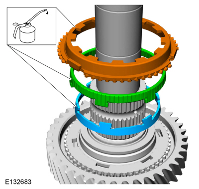
-
Lubricate the 1st gear synchronizer in transmission fluid and install the synchronizer.
Material: Motorcraft® Dual Clutch Transmission Fluid / XT-11-QDC (WSS-M2C200-D2)
 |
-
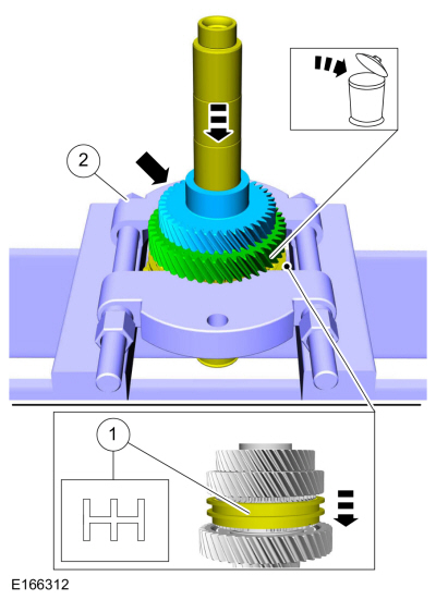
Using the special tools, install the 1st-2nd gear
synchronizer hub. Align the hub with the 1st gear synchronizer.
Use Special Service Tool: 205-D015 (D80L-630-4) Step Plate.
Use the General Equipment: Hydraulic Press
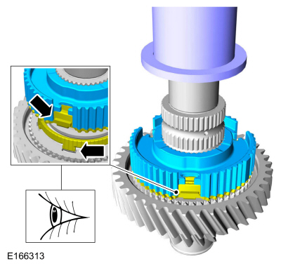 |
-
NOTE: Make sure that the components are installed to the position noted before removal.
-
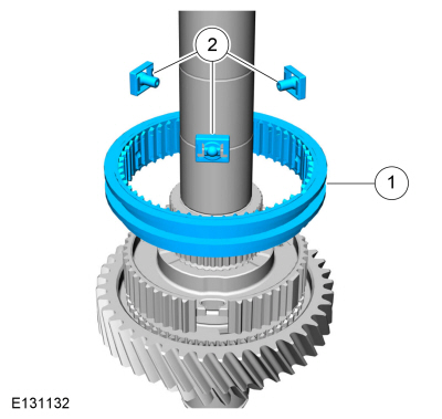
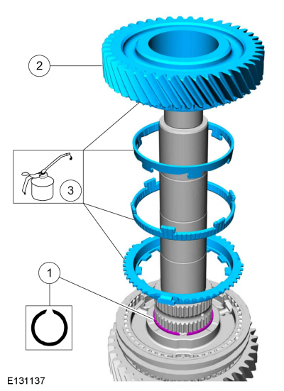
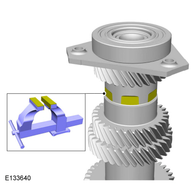
Install the 1st-2nd gear synchronizer sleeve.
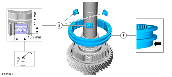
-
Lubricate the 1st-2nd gear synchronizer sleeve
detents in transmission fluid and install them so they fit in the
1st-2nd gear synchronizer hub as shown.
Material: Motorcraft® Dual Clutch Transmission Fluid / XT-11-QDC (WSS-M2C200-D2)
-
Install the 1st-2nd gear synchronizer sleeve.
 |
-
-
Install the 1st-2nd gear synchronizer hub snap ring.
-
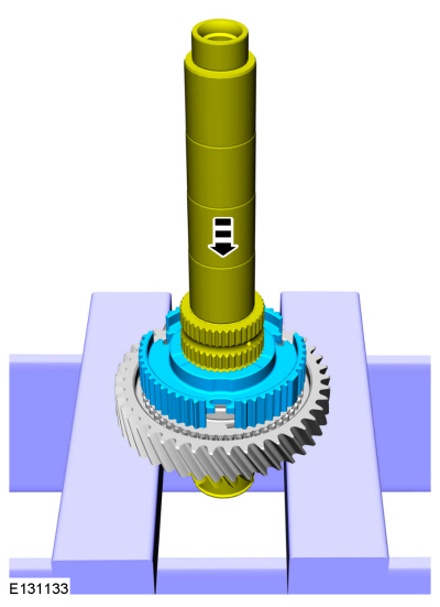
Lubricate the parts in transmission fluid and install the 2nd gear synchronizer assembly.
Material: Motorcraft® Dual Clutch Transmission Fluid / XT-11-QDC (WSS-M2C200-D2)
-
Install 2nd gear.
Material: Motorcraft® Dual Clutch Transmission Fluid / XT-11-QDC (WSS-M2C200-D2)
-
Install the 1st-2nd gear synchronizer hub snap ring.
 |
-
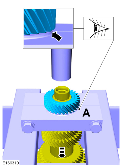
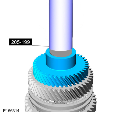
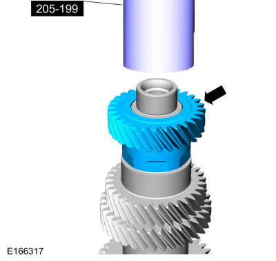
Using the special tools, install 3rd gear.
Use Special Service Tool: 205-199 (T83T-3132-A1) Installer, Spindle/Axle Shaft.
Use the General Equipment: Hydraulic Press
 |
-
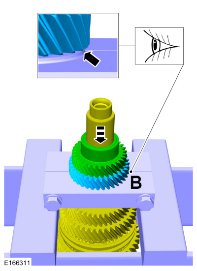
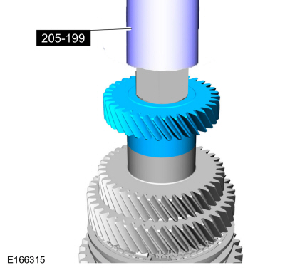
Using the special tools, install 4th gear.
Use Special Service Tool: 205-199 (T83T-3132-A1) Installer, Spindle/Axle Shaft.
Use the General Equipment: Hydraulic Press
 |
-
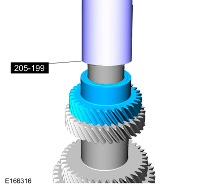
Using the special tools, install 5th gear.
Use Special Service Tool: 205-199 (T83T-3132-A1) Installer, Spindle/Axle Shaft.
Use the General Equipment: Hydraulic Press
 |
-
Using the special tools, install 6th gear.
Use Special Service Tool: 205-199 (T83T-3132-A1) Installer, Spindle/Axle Shaft.
Use the General Equipment: Hydraulic Press
 |
-
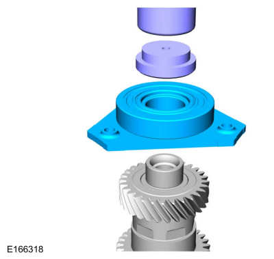
Using the special tool, install the rear bearing.
Use Special Service Tool: 205-D015 (D80L-630-4) Step Plate.
Use the General Equipment: Hydraulic Press
 |
-
NOTICE: Use vise jaw protectors.
Install the output shaft in a vise. Clamp the output shaft on the flat surfaces.
Use the General Equipment: Vise
Use the General Equipment: Vise Jaw Protectors
 |
-
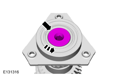
NOTE: The component has a left-hand thread.
Install a new rear bearing bolt.
Torque: 81 lb.ft (110 Nm)
 |

 Reverse Gear Output Shaft. Disassembly and Assembly of Subassemblies
Special Tool(s) /
General Equipment
205-D015
(D80L-630-4)
Step Plate
205-D016
(D80L-630-5)
Step Plate
307-679Installer, Countershaft Needle BearingTKIT-2010D-FLMTKIT-2010D-ROW
308-416Remover/Installer, Thrust Washer Bearing CupTKIT-1999A-F/LTTKIT-1999A-FM/FLM
Hydraulic Press
Puller
Bearing Separator
Materials
..
Other information:
Ford Fiesta 2014 - 2019 Service Manual: Stoplamps. Diagnosis and Testing
Diagnostics in this manual assume a certain skill level and knowledge of Ford-specific diagnostic practices. REFER to: Diagnostic Methods (100-00 General Information, Description and Operation). DTC Chart: BCM BCM DTC Chart BCM Description Action C1A96:24 Brake Light..
Ford Fiesta 2014 - 2019 Service Manual: Cooling Fan Motor and Shroud. Removal and Installation
Removal NOTE: Removal steps in this procedure may contain installation details. Remove the air cleaner. Refer to: Air Cleaner (303-12B Intake Air Distribution and Filtering - 1.6L EcoBoost (132kW/180PS) – Sigma, Removal and Installation). Remove the engine appearance cover. Disconnect the reson..
Categories
- Manuals Home
- Ford Fiesta Service Manual (2014 - 2019)
- Valve Cover. Removal and Installation
- Front Strut and Spring Assembly. Removal and Installation
- Engine Cooling - 1.6L EcoBoost (132kW/180PS) – Sigma
- Maintenance Schedules
- Clutch - 6-Speed Manual Transmission – B6
Brake Master Cylinder. Removal and Installation
Removal
NOTICE: If the fluid is spilled on the paintwork, the affected area must be immediately washed down with cold water.
NOTE: Removal steps in this procedure may contain installation details.
All vehicles
Remove the battery tray.Refer to: Battery Tray - 1.6L Duratec-16V Ti-VCT (88kW/120PS) – Sigma (414-01 Battery, Mounting and Cables, Removal and Installation).
Refer to: Battery Tray - 1.6L EcoBoost (132kW/180PS) – Sigma (414-01 Battery, Mounting and Cables, Removal and Installation).
Disconnect the vacuum tube from the brake booster and detach the routing clip.