Ford Fiesta: Manual Transmission - 6-Speed Manual Transmission – B6 / Reverse Gear Output Shaft. Disassembly and Assembly of Subassemblies
Ford Fiesta 2014 - 2019 Service Manual / Manual Transmission, Clutch, Transfer Case and Power Transfer Unit / Manual Transmission - 6-Speed Manual Transmission – B6 / Reverse Gear Output Shaft. Disassembly and Assembly of Subassemblies
Special Tool(s) / General Equipment
 |
205-D015
(D80L-630-4)
Step Plate |
 |
205-D016
(D80L-630-5)
Step Plate |
 |
307-679 Installer, Countershaft Needle Bearing TKIT-2010D-FLM TKIT-2010D-ROW |
 |
308-416 Remover/Installer, Thrust Washer Bearing Cup TKIT-1999A-F/LT TKIT-1999A-FM/FLM |
| Hydraulic Press | |
| Puller | |
| Bearing Separator | |
Materials
| Name | Specification |
|---|---|
| Motorcraft® Dual Clutch Transmission Fluid XT-11-QDC |
WSS-M2C200-D2 |
DISASSEMBLY
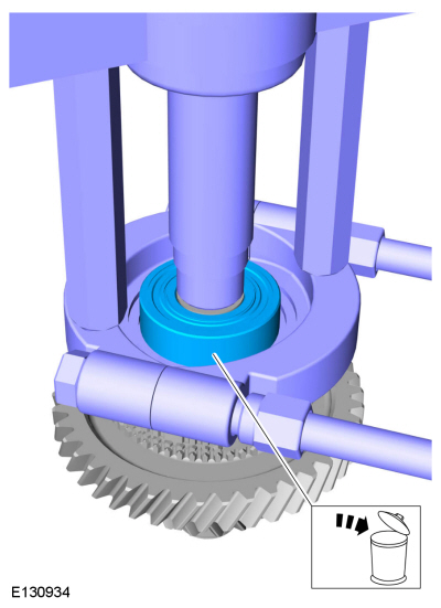
-
Remove the bearing.
Use the General Equipment: Bearing Separator
Use the General Equipment: Puller
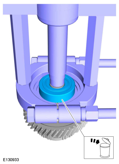 |
-
Remove the bearing.
Use the General Equipment: Bearing Separator
Use the General Equipment: Puller
 |
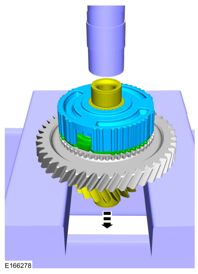
-
Remove the reverse gear synchronizer ring and the synchronizer body.
Use Special Service Tool: 205-D015 (D80L-630-4) Step Plate.
Use the General Equipment: Hydraulic Press
 |
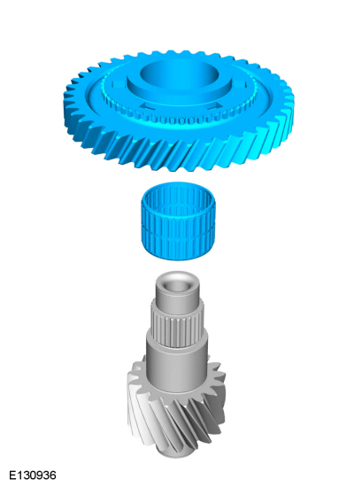
-
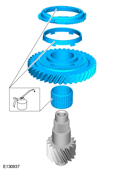
Remove the reverse gear and the needle bearing.
 |
ASSEMBLY
-
Lubricate the reverse gear friction rings.
Material: Motorcraft® Dual Clutch Transmission Fluid / XT-11-QDC (WSS-M2C200-D2)
 |
-
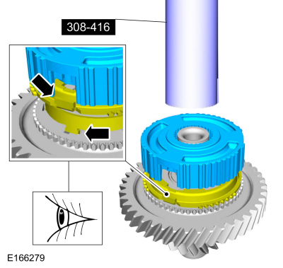
Install the reverse gear synchronizer ring and the
synchronizer body. Make sure the tab on the upper friction ring aligns
with the opening in the synchronizer body and the tabs on the lower
friction ring fit into the reverse gear.
Use Special Service Tool: 308-416 Remover/Installer, Thrust Washer Bearing Cup.
 |
-
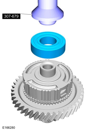
Install the bearing.
Use Special Service Tool: 307-679 Installer, Countershaft Needle Bearing.
Use the General Equipment: Hydraulic Press
 |
-
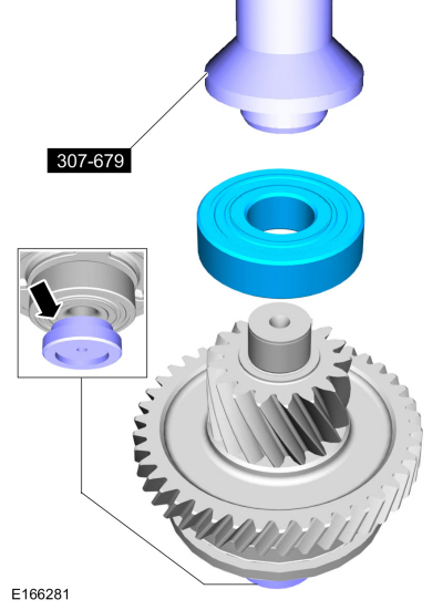
Install the bearing.
Use Special Service Tool: 307-679 Installer, Countershaft Needle Bearing. , 205-D016 (D80L-630-5) Step Plate.
Use the General Equipment: Hydraulic Press
 |

 Transmission. Assembly
Special Tool(s) /
General Equipment
100-002
(TOOL-4201-C)
Holding Fixture with Dial Indicator Gauge
205-075Installer, Rear Wheel Hub Seal
205-081AInstaller, Differential Bearing
205-115Installer, Drive Pinion SealTKIT-2000-F/FM/FLM
303-350
(T89P-6565-A)
Compressor, Valve SpringTKIT-1990-LMHTKIT-1989-FTKIT-1989-FMTKIT-1989-FLM
..
Other information:
Ford Fiesta 2014 - 2019 Service Manual: Rear View Mirrors - Overview. Description and Operation
Overview - Exterior, Power The power mirrors allow the LH and RH exterior mirror glass position to be adjusted electronically by the driver. The exterior mirror glass position is controlled by the exterior mirror control switch. Selecting the LH or RH position of the exterior mirror selection switch determines which power mirror glass to control. Overview - Exterior, Heated Th..
Ford Fiesta 2014 - 2019 Service Manual: Battery Drain Check. General Procedures
Check NOTE: No factory-equipped vehicle should have more than a 25 mA (0.025 amp) – 50 mA (0.050) draw depending on the vehicle's accessories. Check for current drains on the battery in excess of 25 mA (0.025 amp) – 50 mA (0.050) with all the electrical accessories off and the vehicle at rest for at least 40 minutes. Current drains can be tested with the following procedure. ..
Categories
- Manuals Home
- Ford Fiesta Service Manual (2014 - 2019)
- Engine System - General Information
- Front Suspension
- Engine. Assembly
- Engine - 1.6L EcoBoost (132kW/180PS) – Sigma
- Front Strut and Spring Assembly. Removal and Installation
Component Bleeding. General Procedures
Special Tool(s) / General Equipment
Master Cylinder Bleeding SetBleeding
NOTICE: If the fluid is spilled on the paintwork, the affected area must be immediately washed down with cold water.
Master Cylinder
NOTE: When a new brake master cylinder has been installed, it should be primed to prevent air from entering the system.
NOTE: Make sure the area around the master cylinder cap is clean and free of foreign material.
Remove the brake fluid reservoir cap.Copyright © 2026 www.fofiesta7.com