Ford Fiesta: Engine - 1.6L EcoBoost (132kW/180PS) – Sigma / Timing Belt. Removal and Installation
Special Tool(s) /
General Equipment
 |
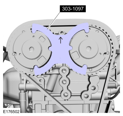
303-1097
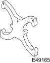
Locking Tool, Variable Camshaft Timing Oil Control Unit
TKIT-2010B-FLM
TKIT-2010B-ROW |
 |
303-1550
Alignment Tool, Crankshaft Vibration Damper
TKIT-2012A-FL
TKIT-2012A-ROW |
 |
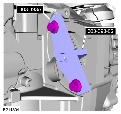
303-393-02
Adapter for 303-393
TKIT-2012A-FL
TKIT-2012A-ROW |
 |
303-393A
Locking Tool, Flywheel
TKIT-2012A-FL
TKIT-2012A-ROW |
 |
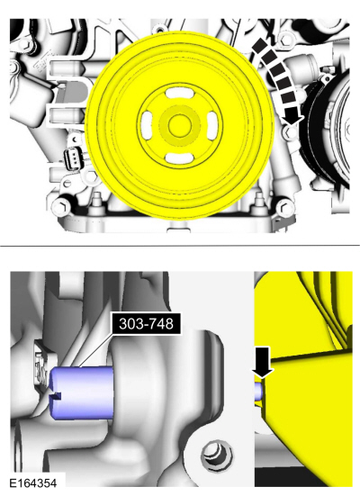
303-748
Locking Tool, Crankshaft
TKIT-2010B-FLM
TKIT-2010B-ROW |
| Trolley Jack |
| Wooden Block |
Removal
NOTICE:
Do not loosen or remove the crankshaft pulley bolt without
first installing the special tools. The crankshaft pulley and the
crankshaft timing sprocket are not keyed to the crankshaft. Before any
repair requiring loosening or removal of the crankshaft pulley bolt, the
crankshaft and camshafts must be locked in place by the special service
tools, otherwise severe engine damage can occur.
NOTE:
During engine repair procedures, cleanliness is extremely
important. Any foreign material, including any material created while
cleaning gasket surfaces, that enters the oil passages, coolant passages
or the oil pan can cause engine failure.
-
With the vehicle in NEUTRAL, position it on a hoist.
Refer to: Jacking and Lifting - Overview (100-02 Jacking and Lifting, Description and Operation).
-
Remove the degas bottle.
Refer to: Degas Bottle (303-03B Engine Cooling - 1.6L EcoBoost (132kW/180PS) – Sigma, Removal and Installation).
-
Remove the engine appearance cover.
-
-
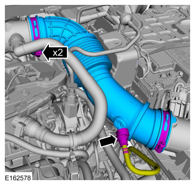
Disconnect the EVAP tube from the air cleaner outlet pipe.
-
Loosen the clamps and remove the air cleaner outlet pipe.
-
NOTICE:
Whenever turbocharger air intake system components
are removed, always cover open ports to protect from debris. It is
important that no foreign material enter the system. The turbocharger
compressor vanes are susceptible to damage from even small particles.
All components should be inspected and cleaned, if necessary, prior to
installation or reassembly.
-
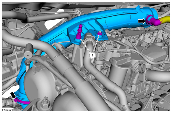
Remove the fasteners.
-
Disconnect the crankcase vent tube from the
turbocharger inlet pipe, loosen the clamp and remove the turbocharger
inlet pipe.
-
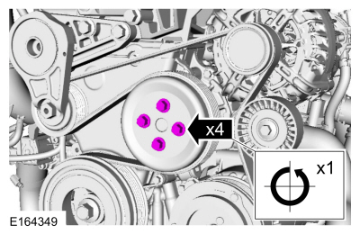
Loosen the coolant pump pulley bolts.
-
Remove the RH front wheel and tire.
Refer to: Wheel and Tire (204-04A Wheels and Tires, Removal and Installation).
-
Remove the retainers and the shield.
-
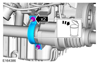
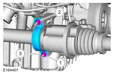
Remove the nuts and discard the halfshaft bracket.
-
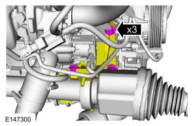
NOTE:
It may be necessary to rotate the halfshaft to remove the front lower bolt.
Remove the bolts and position the bracket aside.
-
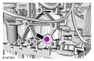
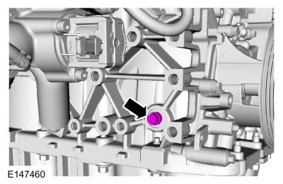
Remove the engine plug bolt.
-
Remove the following items:
-
Remove the starter motor.
Refer to: Starter Motor (303-06B Starting System - 1.6L EcoBoost (132kW/180PS) – Sigma, Removal and Installation).
-
Remove the generator.
Refer to: Generator - 1.6L EcoBoost (132kW/180PS) – Sigma (414-02 Generator and Regulator, Removal and Installation).
-
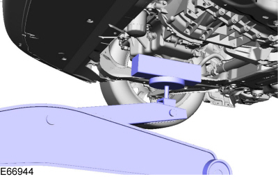
Using the floor jack and a wooden block, support the engine.
Use the General Equipment: Trolley Jack
Use the General Equipment: Wooden Block
-
-
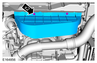
Remove the nuts.
-
Remove the bolts and the engine mount.
-
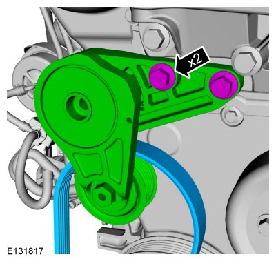
Remove the bolts and the accessory drive tensioner and belt.
-
-
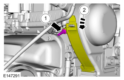
Remove the engine front cover stud bolt.
-
Detach the cover from the retainer and open.
-
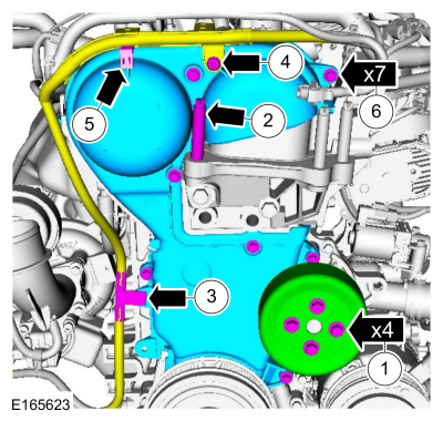
-
Remove the bolts and the coolant pump pulley.
-
Remove the engine mount stud.
-
Detach the wiring harness retainer.
-
Remove the wiring harness mounting clamp retainer.
-
Detach the wiring harness retainer.
-
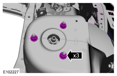
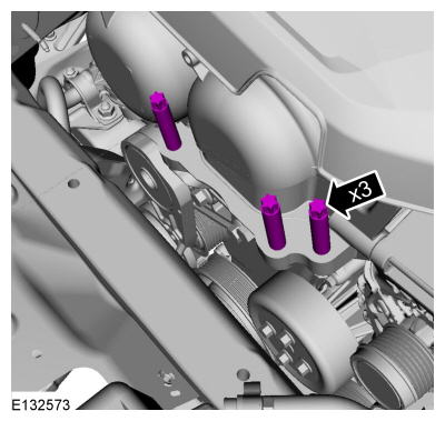
Remove the bolts and the engine front cover.
-
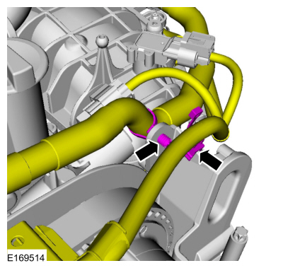
Detach the wiring harness retainers.
-
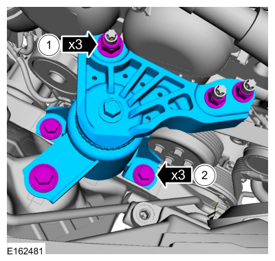
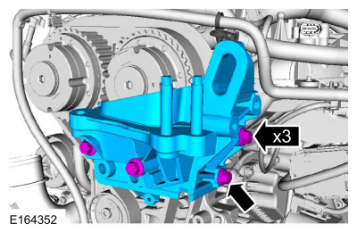
NOTE:
Note the different lengths of the bolts for installation.
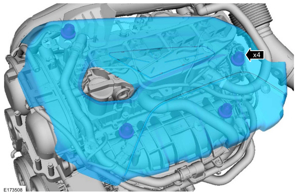
Remove the bolts and the engine mount bracket.
-
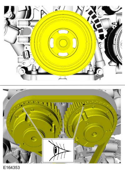
NOTE:
Only rotate the crankshaft in a clockwise direction.
Rotate the VCT units until the timing marks at the 11 o'clock position.
-
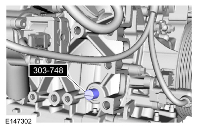
NOTE:
The Crankshaft TDC Timing Pin will contact the crankshaft and prevent
it from turning past TDC . However, the crankshaft can still be rotated
in the counterclockwise direction. The crankshaft must remain at the TDC
position during the crankshaft pulley removal and installation.
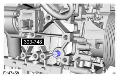
Install Special Service Tool: 303-748
Locking Tool, Crankshaft.
-
NOTE:
Only rotate the crankshaft clockwise direction.
Rotate the crankshaft slowly clockwise until the
crankshaft balance weight is up against the crankshaft locking tool. The
engine is now at TDC .
-
Install Special Service Tool: 303-393-02
Adapter for 303-393.
, 303-393A
Locking Tool, Flywheel.
-
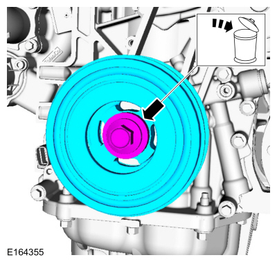
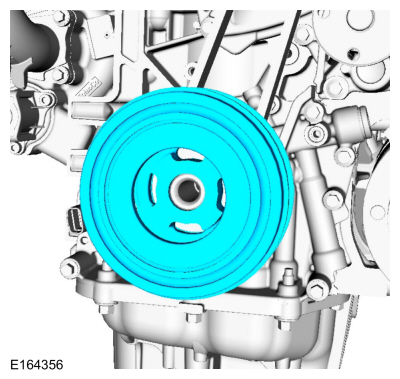
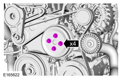
-
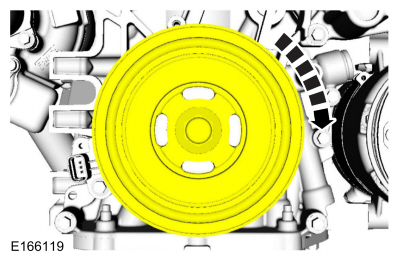
Remove the bolt and the crankshaft pulley.
-
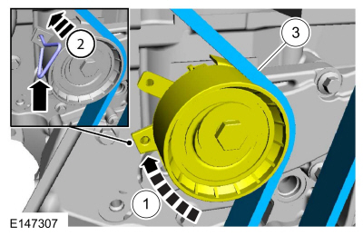
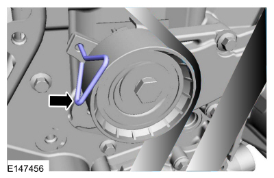
NOTE:
The timing mark of each VCT unit must be at the 12 o'clock position.
NOTE:
It may necessary to rotate the camshafts slightly to install the special tool.
Install Special Service Tool: 303-1097
Locking Tool, Variable Camshaft Timing Oil Control Unit.
-
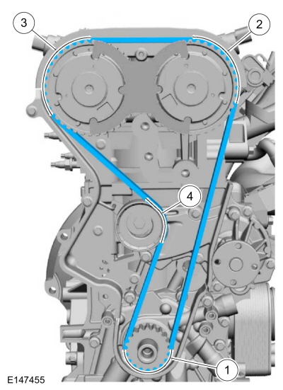
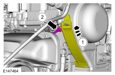
 WARNING:
The timing belt tensioner spring is under load.
Extra care must be taken at all times when handling the tensioner.
Failure to follow this instruction may result in personal injury.
WARNING:
The timing belt tensioner spring is under load.
Extra care must be taken at all times when handling the tensioner.
Failure to follow this instruction may result in personal injury.
Rotate the timing belt tensioner and install a holding pin. Remove the timing belt.
-
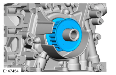
Remove the crankshaft sprocket.
-
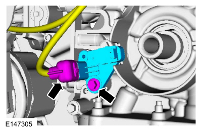
-
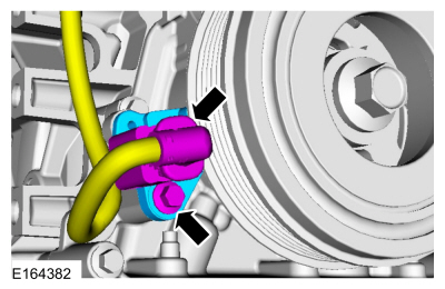
Disconnect the electrical connector.
-
Remove the bolt and the CKP sensor.
Installation
-
NOTE:
Before installation, clean and inspect the sprocket
for any damage. If damage is evident, replace the sprocket. If no
damage, the sprocket is to be reused.
Install the crankshaft sprocket.
-
Install the timing belt.
-
WARNING:
The timing belt tensioner spring is under load.
Extra care must be taken at all times when handling the tensioner.
Failure to follow this instruction may result in personal injury.
Remove the holding pin.
-
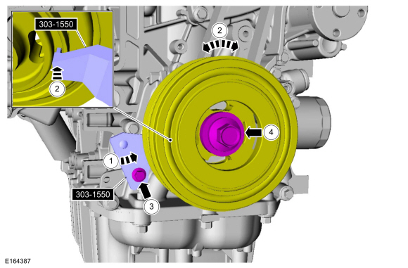
Install the crankshaft pulley.
-
-
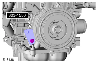
Install Special Service Tool: 303-1550
Alignment Tool, Crankshaft Vibration Damper.
-
Rotate crankshaft pulley to align the Special Tool:
Use Special Service Tool: 303-1550
Alignment Tool, Crankshaft Vibration Damper.
-
Install the bolt finger tight at this stage.
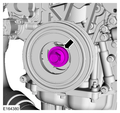
-
Using a new bolt, finger tight at this stage.
-
Tighten the crankshaft pulley bolt.
Torque:
Stage 1:
74 lb.ft (100 Nm)
Stage 2:
90°
Stage 3:
Wait 2s
Stage 4:
15°
-
Remove Special Service Tool: 303-1550
Alignment Tool, Crankshaft Vibration Damper.
-
Remove Special Service Tool: 303-748
Locking Tool, Crankshaft.
-
Remove Special Service Tool: 303-393-02
Adapter for 303-393.
, 303-393A
Locking Tool, Flywheel.
-
Remove Special Service Tool: 303-1097
Locking Tool, Variable Camshaft Timing Oil Control Unit.
-
NOTE:
Only rotate the crankshaft in a clockwise direction.
Rotate the crankshaft pulley about 1 3/4 turns.
-
Install Special Service Tool: 303-748
Locking Tool, Crankshaft.
-
NOTE:
Only rotate the crankshaft in a clockwise direction.
Rotate the crankshaft slowly clockwise until the
crankshaft balance weight is up against the crankshaft locking tool. The
engine is now at TDC .
-
NOTE:
The timing mark of each VCT unit must be at the 12 o'clock position.
NOTE:
It may necessary to rotate the camshafts slightly to install the special tool.
If the special tool cannot be installed, repeat the adjustment according to the preceding steps.
Install Special Service Tool: 303-1097
Locking Tool, Variable Camshaft Timing Oil Control Unit.
-
Remove Special Service Tool: 303-1097
Locking Tool, Variable Camshaft Timing Oil Control Unit.
-
NOTE:
There are different length of bolts noted in removal.
Install the engine mount bracket and the bolts.
Torque:
41 lb.ft (55 Nm)
-
Attach the wiring harness retainers.
-
-
Install the engine front cover and the bolts.
Torque:
89 lb.in (10 Nm)
-
Install the engine mount stud finger-tight.
-
Install the coolant pulley and the bolts finger-tight.
-
Install the wiring harness mounting clamp and the retainer.
Torque:
71 lb.in (8 Nm)
-
Attach the wiring harness retainer.
-
Attach the wiring harness retainer.
-
-
Close the cover and attach the retainer.
-
Install the engine front cover stud bolt.
Torque:
89 lb.in (10 Nm)
-
Install the accessory drive tensioner, belt and the bolts.
Torque:
35 lb.ft (48 Nm)
-
Tighten the engine mount stud bolts.
Torque:
89 lb.in (10 Nm)
-
-
Install the engine mount and the nuts.
Torque:
59 lb.ft (80 Nm)
-
Install the bolts.
Torque:
35 lb.ft (48 Nm)
-
Remove the floor jack and the wooden block.
Use the General Equipment: Trolley Jack
Use the General Equipment: Wooden Block
-
Remove Special Service Tool: 303-748
Locking Tool, Crankshaft.
-
Install the engine plug bolt.
Torque:
177 lb.in (20 Nm)
-
Install the CKP sensor and the bolt, connect the electrical connector.
Torque:
89 lb.in (10 Nm)
-
Position the bracket and install the bolts.
Torque:
35 lb.ft (48 Nm)
-
Install the halfshaft bearing retaining strap and the nuts.
Torque:
Stage 1:
44 lb.in (5 Nm)
Stage 2:
18 lb.ft (24 Nm)
-
Install the following items:
-
Install the generator.
Refer to: Generator - 1.6L EcoBoost (132kW/180PS) – Sigma (414-02 Generator and Regulator, Removal and Installation).
-
Install the starter motor.
Refer to: Starter Motor (303-06B Starting System - 1.6L EcoBoost (132kW/180PS) – Sigma, Removal and Installation).
-
Install the shield and the retainers.
-
Install the RH front wheel and tire.
Refer to: Wheel and Tire (204-04A Wheels and Tires, Removal and Installation).
-
Tighten the coolant pump pulley bolts.
Torque:
18 lb.ft (24 Nm)
-
-
Install the TC inlet pipe and the fasteners. Connect the crankcase vent tube.
Torque:
44 lb.in (5 Nm)
-
Tighten the clamp.
Torque:
44 lb.in (5 Nm)
-
Install the air cleaner outlet pipe and tighten the clamps. Connect the EVAP tube to the air cleaner outlet pipe.
Torque:
44 lb.in (5 Nm)
-
Install the engine appearance cover.
-
Install the degas bottle.
Refer to: Degas Bottle (303-03B Engine Cooling - 1.6L EcoBoost (132kW/180PS) – Sigma, Removal and Installation).
-
After completing the repairs, perform the Misfire Monitor Neutral Profile Correction procedure.
Special Tool(s) /
General Equipment
303-1097Locking Tool, Variable Camshaft Timing Oil Control UnitTKIT-2010B-FLMTKIT-2010B-ROW
Trolley Jack
Wooden Block
Materials
Name
Specification
Motorcraft® Metal Brake Parts CleanerPM-4-A, PM-4-B, APM-4-C
-
Removal
Remove the crankshaft front seal...
Special Tool(s) /
General Equipment
Hot Air Gun
Hose Clamp Remover/Installer
Materials
Name
Specification
Flange SealantCU7Z-19B508-A
WSS-M2G348-A11
Motorcraft® Metal Surface Prep WipesZC-31-B
-
Engine Oil - SAE 5W-20 - Synthetic Blend Motor OilXO-5W20-Q1SP
WSS-M2C945-B1
Removal
Valve Cover Onl..
Other information:
Special Tool(s) /
General Equipment
Air Conditioning Service Unit
Air Conditioning Adaptor Kit
Inspection
Recover the refrigerant. Refer to Air Conditioning (A/C)
System Recovery, Evacuation and Charging procedure in Group 412.
Disconnect the evaporator from the A/C system. Refer to
the appropriate section in Group 412 for the procedure...
Materials
Name
Specification
Motorcraft® Metal Surface Prep WipesZC-31-B
-
Removal
NOTE:
Removal steps in this procedure may contain installation details.
Drain the cooling system.
Refer to: Engine Cooling System Draining, Vacuum Filling and Bleeding
(303-03B Engine Cooling - 1.6L EcoBoost (132kW/180PS) – Sigma, General
Procedure..

 Oil Pump. Removal and Installation
 Valve Cover. Removal and Installation
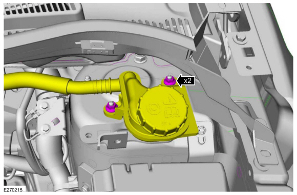 Remove the strut and spring assembly upper mount nuts.