Ford Fiesta: Manual Transmission - 6-Speed Manual Transmission – B6 / Input Shaft. Disassembly and Assembly of Subassemblies
Ford Fiesta 2014 - 2019 Service Manual / Manual Transmission, Clutch, Transfer Case and Power Transfer Unit / Manual Transmission - 6-Speed Manual Transmission – B6 / Input Shaft. Disassembly and Assembly of Subassemblies
Special Tool(s) / General Equipment
 |
205-199
(T83T-3132-A1)
Installer, Spindle/Axle Shaft T83-4000-A TKIT-1983-F TKIT-1983-FLM TKIT-1983-FX |
 |
205-D015
(D80L-630-4)
Step Plate |
 |
211-014 Remover, Steering Wheel |
 |
307-679 Installer, Countershaft Needle Bearing TKIT-2010D-FLM TKIT-2010D-ROW |
| Hydraulic Press | |
| Hot Air Gun | |
| Bearing Separator | |
| Vise | |
| Vise Jaw Protectors | |
Materials
| Name | Specification |
|---|---|
| Motorcraft® Dual Clutch Transmission Fluid XT-11-QDC |
WSS-M2C200-D2 |
DISASSEMBLY
-
-
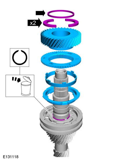
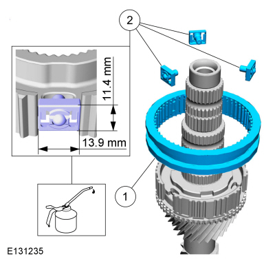
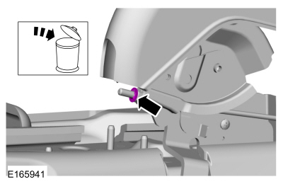
Remove and discard the snap ring.
-
Using the special tools, remove and discard the front bearing.
Use the General Equipment: Hydraulic Press
Use the General Equipment: Bearing Separator
-
Remove and discard the snap ring.
 |
-
NOTICE: Use vise jaw protectors or damage to the splines can occur.
-
Install the input shaft in a vice.
Use the General Equipment: Vise
-
Use vice jaw protectors.
Use the General Equipment: Vise Jaw Protectors
-
Install the input shaft in a vice.
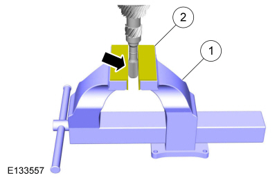 |
-
Heat the bolt to melt the Loctite® and remove and discard the rear bearing bolt.
Use the General Equipment: Hot Air Gun
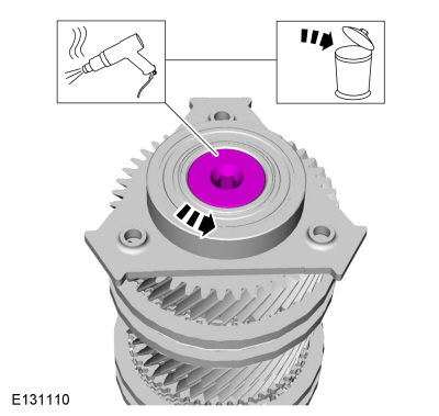 |
-
Using the special tools, remove and discard the rear bearing.
Use Special Service Tool: 211-014 Remover, Steering Wheel.
 |
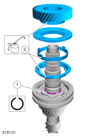
-
Remove 6th gear, 6th gear synchronizer assembly and
remove and discard the 5th-6th gear synchronizer hub snap ring.
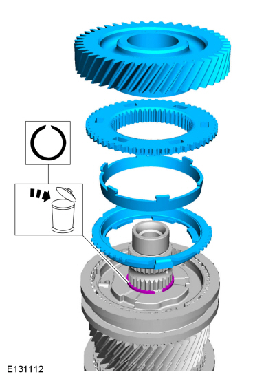 |
-
Remove the 5th-6th gear synchronizer sleeve and the 3 detents.
 |
-
Using the special tools, remove the 5th-6th gear synchronizer hub, 5th gear synchronizer assembly and 5th gear.
Use the General Equipment: Bearing Separator
Use the General Equipment: Hydraulic Press
 |
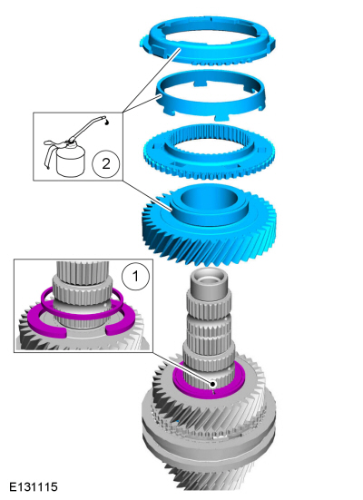
-
NOTE: Note the position of the components before removal.
Remove the 4th gear retainer, 4th gear and the 4th gear synchronizer assembly. Remove and discard the 3rd-4th gear synchronizer hub snap ring.
 |
-
Remove the 3rd-4th gear synchronizer sleeve and the detents.
 |
-
Using the special tools, remove the 3rd-4th gear synchronizer hub, 3rd gear synchronizer assembly, and 3rd gear.
Use the General Equipment: Bearing Separator
Use the General Equipment: Hydraulic Press
 |
-
Remove the 3rd gear bearing.
 |
ASSEMBLY
-
NOTICE: Use vise jaw protectors or damage to the splines can occur.
-
Install the input shaft in a vice.
Use the General Equipment: Vise
-
Use vice jaw protectors.
Use the General Equipment: Vise Jaw Protectors
-
Install the input shaft in a vice.
|
-
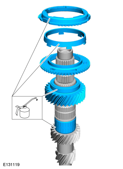
Lubricate the parts in transmission fluid and install
the 3rd gear bearing, 3rd gear and 3rd gear synchronizer assembly.
Material: Motorcraft® Dual Clutch Transmission Fluid / XT-11-QDC (WSS-M2C200-D2)
 |
-
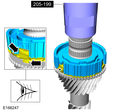
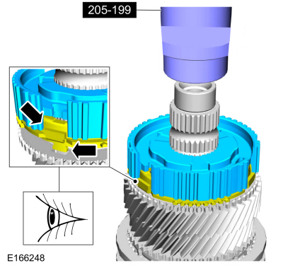
Using the special tools, install the 3rd-4th gear synchronizer hub.
Use Special Service Tool: 205-199 (T83T-3132-A1) Installer, Spindle/Axle Shaft.
 |
-
-
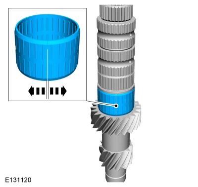
Install the 3rd-4th gear synchronizer sleeve.
-
Lubricate the 3rd-4th gear synchronizer sleeve
detents in transmission fluid and install them so they fit in the
3rd-4th gear synchronizer hub as shown.
Material: Motorcraft® Dual Clutch Transmission Fluid / XT-11-QDC (WSS-M2C200-D2)
-
Install the 3rd-4th gear synchronizer sleeve.
 |
-
-
Install the 3rd-4th gear synchronizer hub snap ring.
-
Lubricate the parts in transmission fluid and
install the 4th gear synchronizer assembly and install 4th gear.
Material: Motorcraft® Dual Clutch Transmission Fluid / XT-11-QDC (WSS-M2C200-D2)
-
Install the 3rd-4th gear synchronizer hub snap ring.
 |
-
-
NOTE: Make sure that the components are installed to the position noted during removal.
Install the 4th gear retainer.
-
Lubricate the parts in transmission fluid and install 5th gear and the 5th gear synchronizer assembly.
Material: Motorcraft® Dual Clutch Transmission Fluid / XT-11-QDC (WSS-M2C200-D2)
-
 |
-
Using the special tools, install the 5th-6th gear synchronizer hub.
Use Special Service Tool: 205-199 (T83T-3132-A1) Installer, Spindle/Axle Shaft.
Use the General Equipment: Hydraulic Press
 |
-
-
Install the 5th-6th gear synchronizer sleeve.
-
Lubricate the 5th-6th gear synchronizer sleeve
detents in transmission fluid and install them so they fit in the
5th-6th gear synchronizer hub as shown.
Material: Motorcraft® Dual Clutch Transmission Fluid / XT-11-QDC (WSS-M2C200-D2)
-
Install the 5th-6th gear synchronizer sleeve.
 |
-
-
Install a new 5th-6th gear synchronizer hub snap ring.
-
Lubricate the parts in transmission fluid and
install the 6th gear synchronizer assembly and install 6th gear.
Material: Motorcraft® Dual Clutch Transmission Fluid / XT-11-QDC (WSS-M2C200-D2)
-
Install a new 5th-6th gear synchronizer hub snap ring.
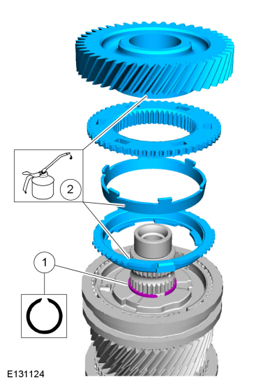 |
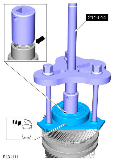
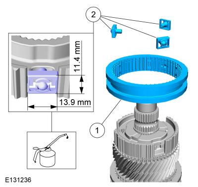
-
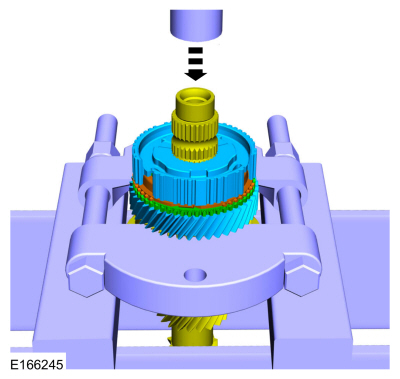
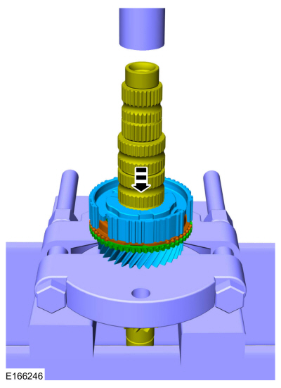
Using the special tools, install the rear bearing.
Use Special Service Tool: 205-D015 (D80L-630-4) Step Plate.
Use the General Equipment: Hydraulic Press
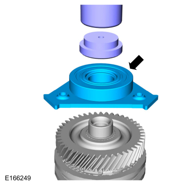 |
-
Install a new rear bearing bolt.
Torque: 81 lb.ft (110 Nm)
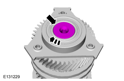 |
-
-
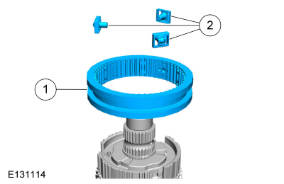
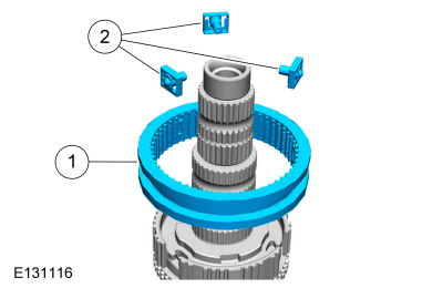
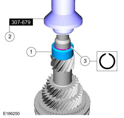
Position the front bearing on the input shaft.
-
Using the special tools, install the front bearing.
Use Special Service Tool: 307-679 Installer, Countershaft Needle Bearing.
Use the General Equipment: Hydraulic Press
-
Install a new snap ring.
-
Position the front bearing on the input shaft.
 |
 Differential. Disassembly and Assembly of Subassemblies
Special Tool(s) /
General Equipment
205-062Installer, Differential Bearing
Puller
Bearing Separator
Materials
Name
Specification
Motorcraft® Dual Clutch Transmission FluidXT-11-QDC
WSS-M2C200-D2
DISASSEMBLY
NOTICE:
Use vise jaw protectors...
 Output Shaft. Disassembly and Assembly of Subassemblies
Special Tool(s) /
General Equipment
205-199
(T83T-3132-A1)
Installer, Spindle/Axle ShaftT83-4000-ATKIT-1983-FTKIT-1983-FLMTKIT-1983-FX
205-D015
(D80L-630-4)
Step Plate
211-014Remover, Steering Wheel
Hydraulic Press
Hot Air Gun
Bearing Separator
Vise
Vise Jaw Protectors
Materials
Name
Specification
..
Other information:
Ford Fiesta 2014 - 2019 Service Manual: Rear Quarter Window Glass - 4-Door. Removal and Installation
Special Tool(s) / General Equipment 300-AST1770EDeluxe Air Knife AST405 Materials Name Specification Sika® SikaTack® MACH 60 / Sika® SikaTack® MACH 30 / Dow® BETASEAL™ Express - Sika Tack ASAP Urethane Adhesive - Dow Urethane One Step Glass PrimerBetaprime™ 5500/5500A/5500SA - Sika Ureth..
Ford Fiesta 2014 - 2019 Service Manual: Front Toe Adjustment. General Procedures
Special Tool(s) / General Equipment Wheel Alignment System Adjustment NOTE: Make sure that the vehicle is standing on a level surface. Using alignment equipment and the manufacturer's instructions, check the front toe setting on both sides. Use the General Equipment: Wheel Alignment System ..
Categories
- Manuals Home
- Ford Fiesta Service Manual (2014 - 2019)
- Maintenance Schedules
- Manual Transmission, Clutch, Transfer Case and Power Transfer Unit
- Jacking and Lifting - Overview. Description and Operation
- Lower Arm. Removal and Installation
- Front Suspension
Parking Brake Control. Removal and Installation
Removal
NOTE: Removal steps in this procedure may contain installation details.
Remove the floor console.Refer to: Floor Console (501-12 Instrument Panel and Console, Removal and Installation).
Remove the driver seat.
Refer to: Front Seat (501-10 Seating, Removal and Installation).
Remove the parking brake cable adjustment lock nut.
 Loosen the parking brake cable adjustment nut.
Copyright © 2026 www.fofiesta7.com