Ford Fiesta: Hydraulic Brake Actuation / Brake Master Cylinder. Removal and Installation
Removal
NOTICE: If the fluid is spilled on the paintwork, the affected area must be immediately washed down with cold water.
NOTE: Removal steps in this procedure may contain installation details.
All vehicles
-
Remove the battery tray.
Refer to: Battery Tray - 1.6L Duratec-16V Ti-VCT (88kW/120PS) – Sigma (414-01 Battery, Mounting and Cables, Removal and Installation).
Refer to: Battery Tray - 1.6L EcoBoost (132kW/180PS) – Sigma (414-01 Battery, Mounting and Cables, Removal and Installation).
-
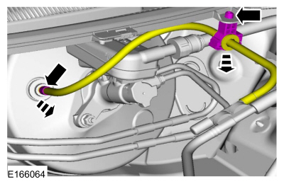
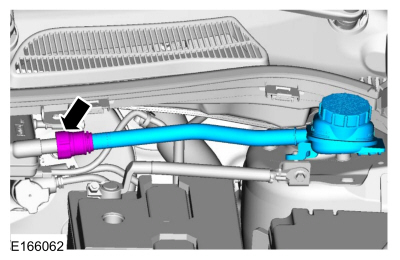
Disconnect the vacuum tube from the brake booster and detach the routing clip.
 |
-
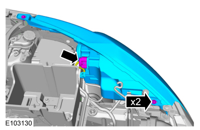
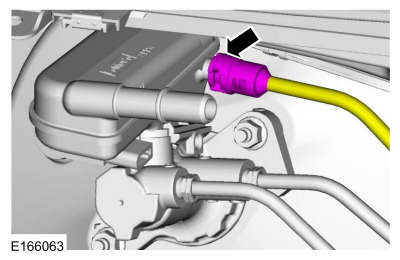
Disconnect the electrical connector, remove the screws and the headlamp assembly.
 |
-
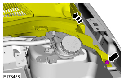
Remove the bolt and position the cowl vent panel upward.
Torque: 19 lb.in (2.2 Nm)
 |
-
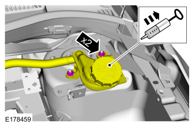
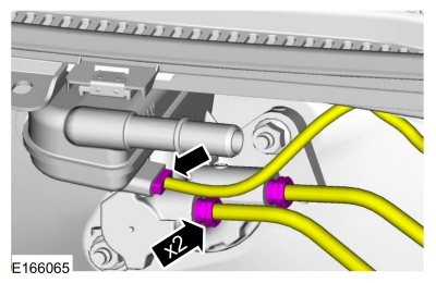
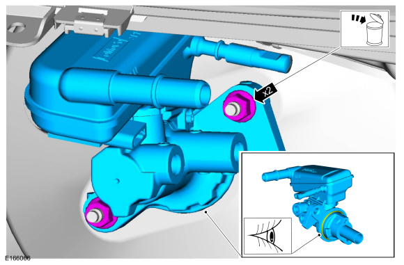
Using a suitable suction device, remove the brake fluid from the remote reservoir and then remove the nuts.
Torque: 62 lb.in (7 Nm)
 |
-
Release the coupling and remove the remote brake fluid reservoir.
 |
Vehicles with manual transmission
-
Release the coupling and disconnect the clutch master cylinder tube.
 |
All vehicles
-
Disconnect the brake fluid level sensor electrical connector and the brake tube fittings.
Torque: 150 lb.in (17 Nm)
 |
-
NOTE: Before installing the master cylinder make sure a new brake booster-to-master cylinder O-ring is in place and the mating faces are clean.
Remove the nuts and the brake master cylinder. Discard the nuts.
Torque: 177 lb.in (20 Nm)
 |
-
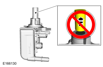
NOTICE: Take extra care when handling the component.
Do not remove the brake master cylinder piston extension.
 |
Installation
All vehicles
-
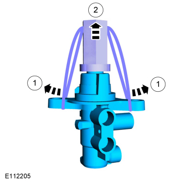
NOTE: This step is only necessary when installing a new component.
Remove the plastic ties and the protective cap.
 |
-
To install, reverse the removal procedure.
-
-
If a new brake master cylinder has been installed, bleed the master cylinder.
Refer to: Component Bleeding (206-00 Brake System - General Information, General Procedures).
-
If the brake master cylinder was removed to access other components, bleed the brake system.
Refer to: Brake System Pressure Bleeding (206-00 Brake System - General Information, General Procedures).
-
If a new brake master cylinder has been installed, bleed the master cylinder.
Vehicles with manual transmission
-
Bleed the clutch system.
Refer to: Clutch System Bleeding (308-02 Clutch Controls - 5-Speed Manual Transmission – B5/IB5/6-Speed Manual Transmission – B6, General Procedures).
 Brake Pedal and Bracket. Removal and Installation
Removal
NOTICE:
Do not service the brake pedal or brake booster without
first removing the stoplamp switch and the cruise control deactivator
switch...
 Brake Fluid Reservoir. Removal and Installation
Materials
Name
Specification
Motorcraft® DOT 4 LV High Performance Motor Vehicle Brake FluidPM-20
WSS-M6C65-A2
Removal
NOTICE:
If the fluid is spilled on the paintwork, the affected area must be immediately washed down with cold water...
Other information:
Ford Fiesta 2014 - 2019 Service Manual: Front Door Window Regulator. Removal and Installation
Removal NOTE: Removal steps may contain installation details. NOTE: Driver side shown, passenger side similar. All vehicles Remove the front door trim panel. Refer to: Front Door Trim Panel (501-05 Interior Trim and Ornamentation, Removal and Installation)...
Ford Fiesta 2014 - 2019 Service Manual: Clutch System Bleeding. General Procedures
Special Tool(s) / General Equipment Brake/Clutch System Pressure Bleeder/Filler Materials Name Specification Motorcraft® DOT 4 LV High Performance Motor Vehicle Brake FluidPM-20 WSS-M6C65-A2 Bleeding NOTE: Make sure that the brake fluid level does not drop below the MIN mark...
Categories
- Manuals Home
- Ford Fiesta Service Manual (2014 - 2019)
- Camshafts. Removal and Installation
- Engine Component View. Description and Operation
- Engine System - General Information
- Cylinder Head. Removal and Installation
- Service Information
Brake Master Cylinder. Removal and Installation
Removal
NOTICE: If the fluid is spilled on the paintwork, the affected area must be immediately washed down with cold water.
NOTE: Removal steps in this procedure may contain installation details.
All vehicles
Remove the battery tray.Refer to: Battery Tray - 1.6L Duratec-16V Ti-VCT (88kW/120PS) – Sigma (414-01 Battery, Mounting and Cables, Removal and Installation).
Refer to: Battery Tray - 1.6L EcoBoost (132kW/180PS) – Sigma (414-01 Battery, Mounting and Cables, Removal and Installation).
Disconnect the vacuum tube from the brake booster and detach the routing clip.