Ford Fiesta: Information and Entertainment System - General Information - Vehicles With: AM/FM/CD/SYNC/Touchscreen Display / Microphone. Removal and Installation
Special Tool(s) / General Equipment
| Interior Trim Remover |
Removal
NOTE: If the microphone is removed from the headliner, a new microphone must be installed.
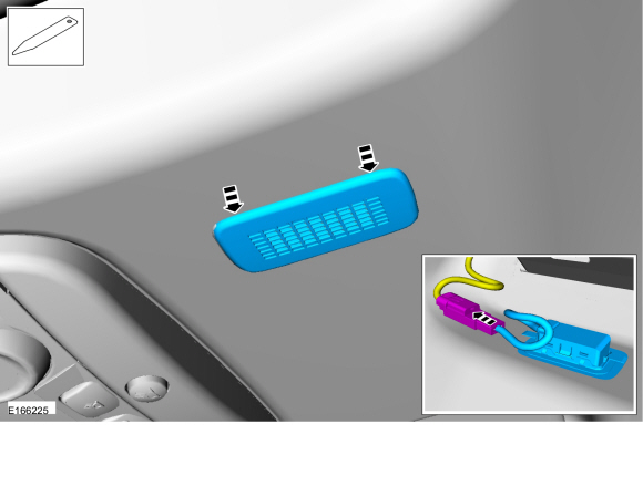
Headliner Microphone
-
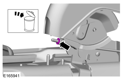
Pry the microphone bezel from the headliner metal mounting bracket and remove the microphone from the headliner by grasping the microphone pigtail.
-
Disconnect the electrical connector.
Use the General Equipment: Interior Trim Remover
-
Disconnect the electrical connector.
 |
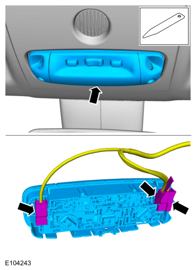
Overhead Console Microphone
NOTE: Overhead console without sunglass bin shown, overhead console with sunglass bin similar.
-
Remove the overhead console lighting switch.
-
Disconnect the electrical connectors.
Use the General Equipment: Interior Trim Remover
-
Disconnect the electrical connectors.
 |
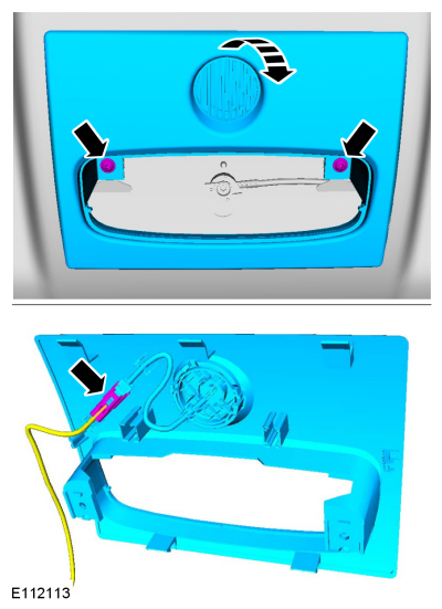
-
Remove the screws and the overhead console.
-
Disconnect the electrical connector.
-
Disconnect the electrical connector.
 |
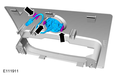
-
Release the tabs, detach the retainer and remove the Sync Microphone.
 |
Installation
Headliner Microphone
-
Connect the microphone electrical connector.
-
Wrap the connection with anti-rattle tape.
-
Feed the microphone pigtail into the headliner
through the microphone hole. Verify the microphone pigtail points
towards the front of the vehicle.
-
Snap the microphone into the headliner mounting bracket.
-
Install the headliner mounting bracket in the headliner.
Overhead Console Microphone
-
To install, reverse the removal procedure.
 Front Door Speaker. Removal and Installation
Removal
NOTE:
Removal steps in this procedure may contain installation details.
Remove the front door trim panel.
Refer to: Front Door Trim Panel (501-05 Interior Trim and Ornamentation, Removal and Installation)...
 Rear Door Speaker. Removal and Installation
Removal
NOTE:
Removal steps in this procedure may contain installation details.
Remove the rear door trim panel.
Refer to: Rear Door Trim Panel (501-05 Interior Trim and Ornamentation, Removal and Installation)...
Other information:
Ford Fiesta 2014 - 2019 Service Manual: Instrument Panel and Interior Switches Illumination - System Operation and Component Description. Description and Operation
System Operation System Diagram Item Description 1 MS-CAN 2 Infotainment Controller Area Network (I-CAN) 3 LIN 4 FCIM 5 IPC 6 APIM 7 FCDIM 8 Seat heater switch, passenger 9 Seat heater switch, driver 10 BCM ..
Ford Fiesta 2014 - 2019 Service Manual: Turn Signal and Hazard Lamps. Diagnosis and Testing
Diagnostics in this manual assume a certain skill level and knowledge of Ford-specific diagnostic practices. REFER to: Diagnostic Methods (100-00 General Information, Description and Operation). DTC Chart: BCM BCM DTC Chart DTC Description Action B123A:11 Left Front..
Categories
- Manuals Home
- Ford Fiesta Service Manual (2014 - 2019)
- Clutch - 6-Speed Manual Transmission – B6
- Maintenance Schedules
- Camshafts. Removal and Installation
- Manual Transmission, Clutch, Transfer Case and Power Transfer Unit
- Front Suspension
Parking Brake Control. Removal and Installation
Removal
NOTE: Removal steps in this procedure may contain installation details.
Remove the floor console.Refer to: Floor Console (501-12 Instrument Panel and Console, Removal and Installation).
Remove the driver seat.
Refer to: Front Seat (501-10 Seating, Removal and Installation).
Remove the parking brake cable adjustment lock nut.
 Loosen the parking brake cable adjustment nut.
Copyright © 2026 www.fofiesta7.com