Ford Fiesta: Handles, Locks, Latches and Entry Systems / Ignition Lock Cylinder. Removal and Installation
Ford Fiesta 2014 - 2019 Service Manual / Body and Paint / Handles, Locks, Latches and Entry Systems / Ignition Lock Cylinder. Removal and Installation
Removal
Non-functional lock cylinder
NOTE: For non-functional ignition lock cylinders, replace the ingition lock cylinder housing.
-
Replace the ingition lock cylinder housing.
Refer to: Ignition Lock Cylinder Housing (211-05 Steering Wheel and Column Electrical Components, Removal and Installation).
Functional lock cylinder
-
Remove the Passive Anti-Theft System Transceiver (PATS).
Refer to: Passive Anti-Theft System (PATS) Transceiver (419-01B Passive Anti-Theft System (PATS) - Vehicles Without: Keyless Entry and Push Button Start, Removal and Installation).
Refer to: Passive Anti-Theft System (PATS) Transceiver (419-01C Passive Anti-Theft System (PATS) - Vehicles With: Keyless Entry and Push Button Start, Removal and Installation).
-
Remove the ignition lock cylinder.
-
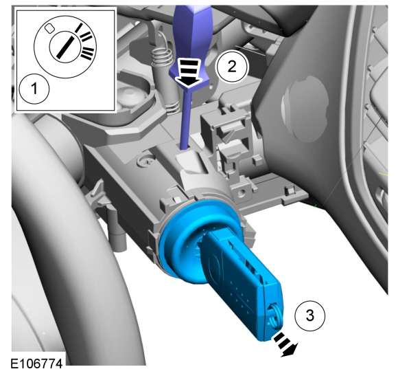
Insert the ignition key and position the ignition lock cylinder to the ACC position.
-
Using a suitable tool, press the ignition lock cylinder release pin through the access hole.
-
Pulling the ignition lock cylinder outward, remove the ignition lock cylinder.
-
Insert the ignition key and position the ignition lock cylinder to the ACC position.
 |
Installation
-
Make sure the ignition lock cylinder is in the ACC position.
-
Insert the ignition lock cylinder into the ignition lock
cylinder access hole located on the steering column. Make sure to align
the locking pin with the locking pin access hole.
-
Rotate the ignition key through all lock cylinder positions to check for correct operation.
-
Install the Passive Anti-Theft System Transceiver (PATS).
Refer to: Passive Anti-Theft System (PATS) Transceiver (419-01B Passive Anti-Theft System (PATS) - Vehicles Without: Keyless Entry and Push Button Start, Removal and Installation).
Refer to: Passive Anti-Theft System (PATS) Transceiver (419-01C Passive Anti-Theft System (PATS) - Vehicles With: Keyless Entry and Push Button Start, Removal and Installation).
 Front Door Lock Cylinder. Removal and Installation
Removal
NOTE:
LH side shown, RH side similar.
Remove the access plug and loosen the exterior front door handle retaining screw...
 Front Door Latch. Removal and Installation
Removal
NOTE:
Removal steps may contain installation details.
NOTE:
Driver side shown, passenger side similar.
All vehicles
Remove the front door trim panel...
Other information:
Ford Fiesta 2014 - 2019 Service Manual: Specifications
General Specifications Item Specification Normal engine cranking speed (Average) 200-250 RPM Starting circuit maximum voltage drop (Engine at normal operating temperature) (Average) 0...
Ford Fiesta 2014 - 2019 Service Manual: 3rd-4th Gear Synchronizer. Removal and Installation
Special Tool(s) / General Equipment 205-199 (T83T-3132-A1) Installer, Spindle/Axle ShaftT83-4000-ATKIT-1983-FTKIT-1983-FLMTKIT-1983-FX 205-D015 (D80L-630-4) Step Plate 211-014Remover, Steering Wheel 307-003 (T57L-500-B) Holding Fixture, Transmission 307-680Table, Assembly (DPS6)TKIT-2010D-FLMTKIT-2010D-ROW 308-847Instal..
Categories
- Manuals Home
- Ford Fiesta Service Manual (2014 - 2019)
- Service Information
- Maintenance Schedules
- Engine
- Engine. Assembly
- Clutch - 6-Speed Manual Transmission – B6
Brake Backing Plate. Removal and Installation
Removal
NOTE: Removal steps in this procedure may contain installation details.
Remove the brake shoes.Refer to: Brake Shoes (206-02 Drum Brake, Removal and Installation).
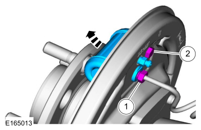
Disconnect the brake tube fitting.
Torque: 159 lb.in (18 Nm) Remove the bolt and wheel cylinder.
Torque: 106 lb.in (12 Nm)
 Disconnect the brake shoe lever fitting and re
Copyright © 2026 www.fofiesta7.com