Ford Fiesta: Information and Entertainment System - General Information - Vehicles With: AM/FM/CD/SYNC/Touchscreen Display / Audio Front Control Module (ACM). Removal and Installation
Removal
NOTE: Removal steps in this procedure may contain installation details.
-
NOTE: This step is only necessary when installing a new component.
NOTE: The PMI process must begin with the current ACM installed. If the current ACM does not respond to the daignostic scan tool, the tool may propmt for As-Built Data as part of the repair.
Using a diagnostic scan tool, begin the PMI process for the ACM following the on-screen instructions.
-
Remove the FCIM .
Refer to: Front Controls Interface Module (FCIM) (415-00B Information and Entertainment System - General Information - Vehicles With: AM/FM/CD/SYNC/Touchscreen Display, Removal and Installation).
-
Remove the ACM bolts.
Torque: 22 lb.in (2.5 Nm)
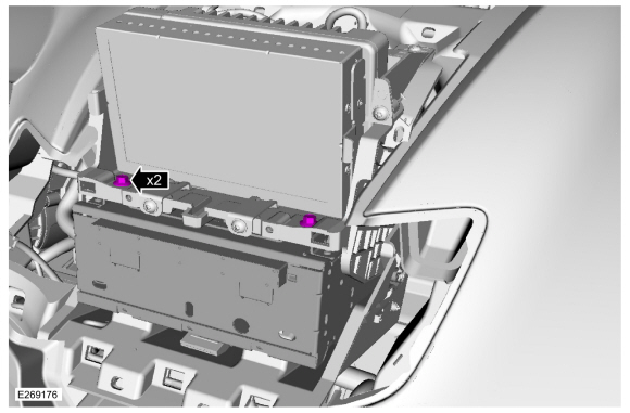 |
-
NOTE: Using both thumbs and pressing up releases the front of the center divider from the instrument panel.
Position the FDIM up.
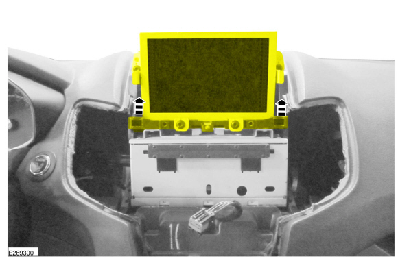 |
-
Remove the ACM .
-
Disconnect the electrical connectors.
-
Disconnect the electrical connectors.
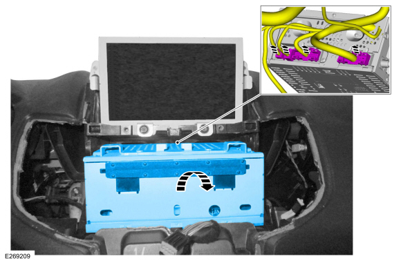 |
Installation
-
To install, reverse the removal procedure.
-
NOTE: This step is only necessary when installing a new component.
Using a diagnostic scan tool, complete the PMI process for the ACM following the on-screen instructions.
 Audio Unit Antenna Cable. Removal and Installation
Removal
NOTE:
Removal steps in this procedure may contain installation details.
Front cable
Remove the ACM .
Refer to: Audio Front Control Module (ACM)
(415-00B Information and Entertainment System - General Information -
Vehicles With: AM/FM/CD/SYNC/Touchscreen Display, Removal and
Installation)...
 Front Controls Interface Module (FCIM). Removal and Installation
Special Tool(s) /
General Equipment
Interior Trim Remover
Removal
NOTE:
Removal steps in this procedure may contain installation details...
Other information:
Ford Fiesta 2014 - 2019 Service Manual: Turn Signal and Hazard Lamps. Diagnosis and Testing
Diagnostics in this manual assume a certain skill level and knowledge of Ford-specific diagnostic practices. REFER to: Diagnostic Methods (100-00 General Information, Description and Operation). DTC Chart: BCM BCM DTC Chart DTC Description Action B123A:11 Left Front..
Ford Fiesta 2014 - 2019 Service Manual: Rear Door Latch. Removal and Installation
Removal NOTE: RH shown, LH similar. NOTE: Removal steps in this procedure may contain installation details. All vehicles Remove the rear door trim panel. Refer to: Rear Door Trim Panel (501-05 Interior Trim and Ornamentation, Removal and Installation). Remove the adhesive tape covers. Vehicles with ..
Categories
- Manuals Home
- Ford Fiesta Service Manual (2014 - 2019)
- Engine
- Engine System - General Information
- Front Suspension
- Fuel Pump. Removal and Installation
- Engine Component View. Description and Operation
Brake Drum. Removal and Installation
Removal
NOTE: Removal steps in this procedure may contain installation details.
 WARNING:
Before beginning any service procedure in this
manual, refer to health and safety warnings in section 100-00 General
Information. Failure to follow this instruction may result in serious
personal injury.
WARNING:
Before beginning any service procedure in this
manual, refer to health and safety warnings in section 100-00 General
Information. Failure to follow this instruction may result in serious
personal injury.
Remove the wheel and tire.
Refer to: Wheel and Tire (204-04A Wheels and Tires, Removal and Installation).