Ford Fiesta: Information and Entertainment System - General Information - Vehicles With: AM/FM/CD/SYNC/Touchscreen Display / Audio Unit Antenna Cable. Removal and Installation
Ford Fiesta 2014 - 2019 Service Manual / Information and Entertainment Systems / Information and Entertainment System - General Information - Vehicles With: AM/FM/CD/SYNC/Touchscreen Display / Audio Unit Antenna Cable. Removal and Installation
Removal
NOTE: Removal steps in this procedure may contain installation details.
Front cable
-
Remove the ACM .
Refer to: Audio Front Control Module (ACM) (415-00B Information and Entertainment System - General Information - Vehicles With: AM/FM/CD/SYNC/Touchscreen Display, Removal and Installation).
-
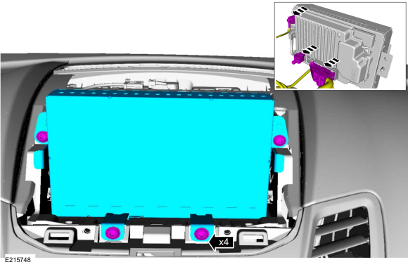
Remove the bolts and the FDIM .
-
Disconnect the electrical connectors.
Torque: 14 lb.in (1.6 Nm)
-
Disconnect the electrical connectors.
 |
-
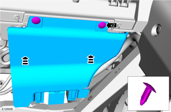
Remove the push pins and the lower RH instrument panel insulator panel.
 |
-
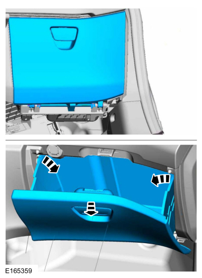
Remove the glove compartment.
 |
-
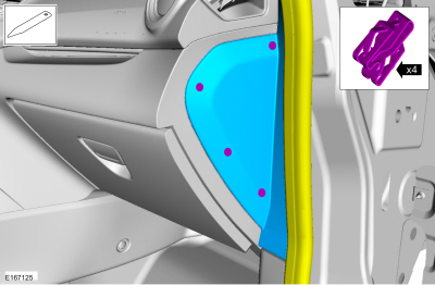
Remove the RH instrument panel side trim panel.
-
Position aside the weather strip.
-
Position aside the weather strip.
 |
-
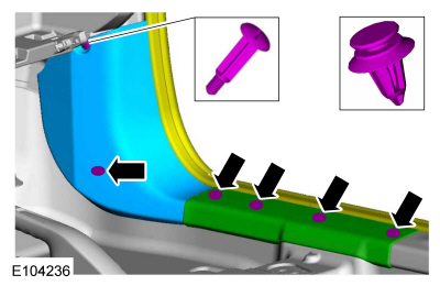
Release the retainers and remove the RH lower cowl trim panel and sill plate.
-
Position aside the weather strip.
-
Position aside the weather strip.
 |
-
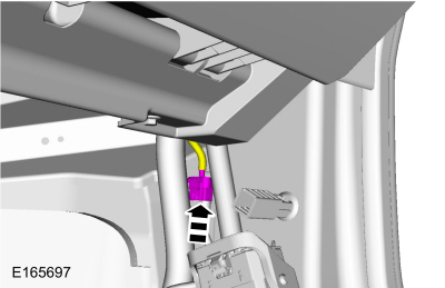
Disconnect the AM/FM/Satellite radio antenna at the lower RH cowl.
 |
-
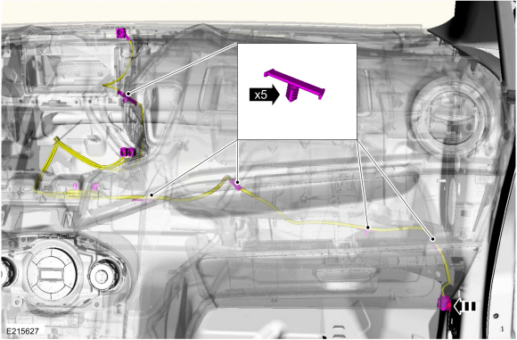
Remove the AM/FM/Satellite radio front antenna cable following the routing shown.
 |
Rear cable
NOTE: The rear AM/FM/Satellite radio antenna cable is part of the vehicle wiring harness. Because the cable cannot be removed from the harness, this procedure applies to the replacement of the cables only.
-
Carefully lower the headliner.
Refer to: Headliner - 4-Door (501-05 Interior Trim and Ornamentation, Removal and Installation).
Refer to: Headliner - 5-Door (501-05 Interior Trim and Ornamentation, Removal and Installation).
-
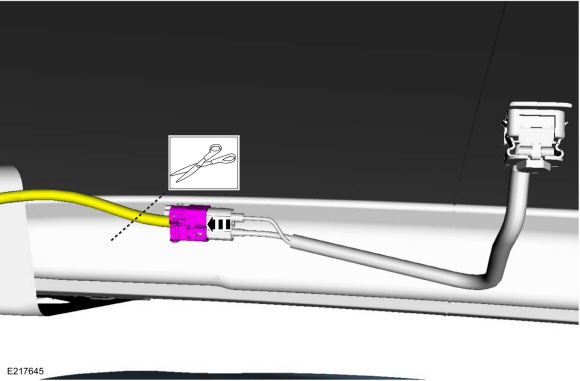
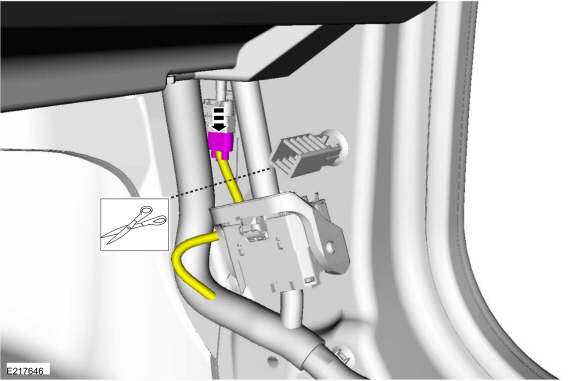
Cut the end off the existing cable.
 |
-
Remove the RH instrument panel side trim panel.
-
Position aside the weather strip.
-
Position aside the weather strip.
 |
-
Release the retainers and remove the RH lower cowl trim panel and sill plate.
-
Position aside the weather strip.
-
Position aside the weather strip.
|
-
Disconnect the AM/FM/Satellite radio antenna at the lower RH cowl.
-
Cut the ends off the exisiting cable.
-
Cut the ends off the exisiting cable.
 |
Installation
Front cable
-
To install, reverse the removal procedure.
Rear cable
-
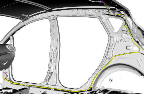
Overlay the new AM/FM/Satellite radio rear antenna
cable on the vehicle wiring harness, following the routing shown. Secure
the new AM/FM/Satellite radio rear antenna cable to the wiring harness
with tape or zip ties as necessary.
 |
-
To install, reverse the removal procedure.
 Audio Unit Antenna. Removal and Installation
Removal
NOTE:
Removal steps in this procedure may contain installation details.
Lower the headliner.
Refer to: C-Pillar Upper Trim Panel - 4-Door (501-05 Interior Trim and Ornamentation, Removal and Installation)...
 Audio Front Control Module (ACM). Removal and Installation
Removal
NOTE:
Removal steps in this procedure may contain installation details.
NOTE:
This step is only necessary when installing a new component...
Other information:
Ford Fiesta 2014 - 2019 Service Manual: Engine Cooling. Diagnosis and Testing
Materials Name Specification Motorcraft® Orange Prediluted Antifreeze/CoolantVC-3DIL-B WSS-M97B44-D2 Motorcraft® Orange Concentrated Antifreeze/CoolantVC-3-B WSS-M97B44-D Special Tool(s) 3-Way HD Antifreeze Coolant Test Kit328-2050-62291 or equivalent Coolant/Battery Refractometer300-ROB75240 or equi..
Ford Fiesta 2014 - 2019 Service Manual: A-Pillar Outer Panel. Removal and Installation
Special Tool(s) / General Equipment Resistance Spotwelding Equipment Hot Air Gun Air Body Saw 8 mm Drill Bit MIG/MAG Welding Equipment Spot Weld Drill Bit Materials Name Specification Metal Bonding AdhesiveTA-1, TA-1-B, 3M™ 08115, LORD Fusor® 108B, Henkel Teroson EP 5055 - Seam SealerTA-2-B, 3M™ 08308, ..
Categories
- Manuals Home
- Ford Fiesta Service Manual (2014 - 2019)
- Front Strut and Spring Assembly. Removal and Installation
- Engine. Assembly
- Timing Belt. Removal and Installation
- Engine Component View. Description and Operation
- Fuel Pump. Removal and Installation
Rear Wheel Speed Sensor. Removal and Installation
Removal
NOTE: Removal steps in this procedure may contain installation details.
Remove the retainer and pull the rear splash shield outward.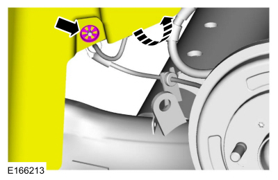 Disconnect the electrical connector and detach the wiring retainer.
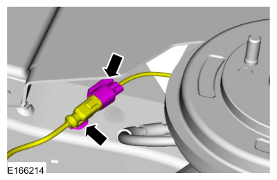
Copyright © 2026 www.fofiesta7.com