Ford Fiesta: Exterior Lighting / Turn Signal and Hazard Lamps. Diagnosis and Testing
Diagnostics in this manual assume a certain skill level and knowledge of Ford-specific diagnostic practices.
REFER to: Diagnostic Methods (100-00 General Information, Description and Operation).
DTC Chart: BCM
BCM
DTC Chart
|
DTC
|
Description
|
Action
|
|
B123A:11
|
Left Front Turn Indicator: Circuit Short to Ground
|
GO to Pinpoint Test C
|
|
B123A:15
|
Left Front Turn Indicator: Circuit Short to Battery or Open
|
GO to Pinpoint Test C
|
|
B123B:11
|
Right Front Turn Indicator: Circuit Short to Ground
|
GO to Pinpoint Test C
|
|
B123B:15
|
Right Front Turn Indicator: Circuit Short to Battery or Open
|
GO to Pinpoint Test C
|
|
B1247:11
|
Left Rear Turn Indicator: Circuit Short to Ground
|
GO to Pinpoint Test C
|
|
B1247:15
|
Left Rear Turn Indicator: Circuit Short to Battery or Open
|
GO to Pinpoint Test C
|
|
B1248:11
|
Right Rear Turn Indicator: Circuit Short to Ground
|
GO to Pinpoint Test C
|
|
B1248:15
|
Right Rear Turn Indicator: Circuit Short to Battery or Open
|
GO to Pinpoint Test C
|
|
B1D35:23
|
Hazard Switch: Signal Stuck Low
|
GO to Pinpoint Test D
|
|
B1D36:92
|
Turn Indicator Switch: Performance or Incorrect Operation
|
GO to Pinpoint Test B
|
|
U3000:49
|
Control Module: Internal Electronic Failure
|
The module has permanently disabled an
output because an excessive current draw fault (such as a short to
ground) has exceeded the limits that the BCM can withstand. The cause of
the excessive current draw MUST be corrected before a new BCM
is installed. ADDRESS all other Diagnostic Trouble Codes (DTCs) first.
After the cause of the concern is corrected, INSTALL a new BCM .
REFER to: Body Control Module (BCM) (419-10 Multifunction Electronic Modules, Removal and Installation).
For additional information on BCM Field Effect Transistor (FET) protection,
REFER
to: Module Controlled Functions - System Operation and Component
Description (419-10 Multifunction Electronic Modules, Description and
Operation).
|
Symptom Chart(s)
Diagnostics in this manual assume a certain skill level and knowledge of Ford-specific diagnostic practices.
REFER to: Diagnostic Methods (100-00 General Information, Description and Operation).
Symptom Chart: Turn Signal and Hazard Lamps
Symptom Chart
|
Condition
|
Possible Sources
|
Actions
|
|
A module does not respond to the diagnostic scan tool
|
-
Fuse
-
Wiring, terminals or connectors
-
Module
|
REFER to: Communications Network (418-00 Module Communications Network, Diagnosis and Testing).
|
|
The turn signal function is inoperative
|
Refer to the Pinpoint test
|
GO to Pinpoint Test A
|
|
The turn signal function is always on
|
Refer to the Pinpoint test
|
GO to Pinpoint Test B
|
|
One turn signal lamp is inoperative or always on
|
Refer to the Pinpoint test
|
GO to Pinpoint Test C
|
|
The hazard lamp function is inoperative or always on
|
Refer to the Pinpoint test
|
GO to Pinpoint Test D
|
Pinpoint Tests
The Turn Signal Function Is Inoperative
Refer to Wiring Diagrams Cell 90 for schematic and connector information.
Normal Operation and Fault Conditions
REFER to: Exterior Lighting - System Operation and Component Description (417-01 Exterior Lighting, Description and Operation).
Possible Sources
-
Fuse
-
Wiring, terminals or connectors
-
Multifunction switch
-
BCM
Visual Inspection and Diagnostic Pre-checks
-
Verify BJB fuse 39 (15A) is OK.
PINPOINT TEST A: THE TURN SIGNAL FUNCTION IS INOPERATIVE
| A1 CHECK THE BCM (BODY CONTROL MODULE)
TURN SIGNAL SWITCH INPUT |
-
Using a diagnostic scan tool, view BCM Parameter Identifications (PIDs).
-
Monitor the BCM TRN_SIG_SW_L and TRN_SIG_SW_R Parameter Identifications (PIDs).
-
Place the LH multifunction switch in the left turn position, right turn position and center position.
Do the BCM TRN_SIG_SW_L and TRN_SIG_SW_R Parameter Identifications (PIDs) change to On when selected?
| Yes |
VERIFY the BJB fuse 39 (15A) is OK. If OK, GO to A4
If not OK, REFER to the Wiring Diagrams manual to identify the possible
causes of the circuit short.
|
| No |
If both the TRN_SIG_SW_L and TRN_SIG_SW_R Parameter Identifications (PIDs) are always Off, GO to A2
If only one of the TRN_SIG_SW_L or TRN_SIG_SW_R Parameter Identifications (PIDs) are always Off, GO to A3
|
|
| A2 CHECK THE LH (LEFT-HAND)
MULTIFUNCTION SWITCH GROUND FOR AN OPEN |
-
Disconnect: LH Multifunction Switch C202.
-
Measure:
Click to display connectors
|
Positive Lead
|
Measurement / Action
|
Negative Lead
|
|
C202-9
|

|
Ground
|
Is the resistance less than 3 ohms?
| Yes |
CARRY OUT the Multifunction Switch component test.
Refer to Wiring Diagrams Cell 149 for schematic and connector information.
If the multifunction switch tests bad, INSTALL a new LH multifunction switch.
REFER
to: Steering Column Multifunction Switch LH (211-05 Steering Wheel and
Column Electrical Components, Removal and Installation).
If the LH multifunction switch tests good, GO to A4
|
|
| A3 CHECK THE BCM (BODY CONTROL MODULE)
TURN SIGNAL SWITCH INPUT CIRCUITS FOR AN OPEN |
-
Disconnect: LH Multifunction Switch C202.
-
Measure:
Click to display connectors
LH Turn Lamp
|
Positive Lead
|
Measurement / Action
|
Negative Lead
|
|
C202-4
|
|
C2280F-15
|
Click to display connectors
RH Turn Lamp
|
Positive Lead
|
Measurement / Action
|
Negative Lead
|
|
C202-8
|
|
C2280F-16
|
Is the resistance less than 3 ohms?
| Yes |
CARRY OUT the Multifunction Switch component test. REFER to
Refer to Wiring Diagrams Cell 149 for schematic and connector information.
If the multifunction switch tests bad, INSTALL a new LH multifunction switch.
REFER
to: Steering Column Multifunction Switch LH (211-05 Steering Wheel and
Column Electrical Components, Removal and Installation).
If the LH multifunction switch tests good, GO to A4
|
|
| A4 CHECK FOR CORRECT BCM (BODY CONTROL MODULE)
OPERATION |
-
Disconnect and inspect all BCM connectors.
-
Repair:
-
corrosion (install new connector or terminals – clean module pins)
-
damaged or bent pins – install new terminals/pins
-
pushed-out pins – install new pins as necessary
-
Reconnect the BCM connectors. Make sure they seat and latch correctly.
-
Operate the system and determine if the concern is still present.
Is the concern still present?
| Yes |
CHECK OASIS for any applicable Technical Service Bulletins (TSBs). If a
TSB exists for this concern, DISCONTINUE this test and FOLLOW TSB
instructions. If no Technical Service Bulletins (TSBs) address this
concern, INSTALL a new BCM .
REFER to: Body Control Module (BCM) (419-10 Multifunction Electronic Modules, Removal and Installation).
|
| No |
The system is operating correctly at this time. The
concern may have been caused by module connections. ADDRESS the root
cause of any connector or pin issues.
|
|
The Turn Signal Function Is Always On
Refer to Wiring Diagrams Cell 90 for schematic and connector information.
Normal Operation and Fault Conditions
REFER to: Exterior Lighting - System Operation and Component Description (417-01 Exterior Lighting, Description and Operation).
DTC Fault Trigger Conditions
|
DTC
|
Description
|
Fault Trigger Conditions
|
|
B1D36:92
|
Turn Indicator Switch: Performance or Incorrect Operation
|
A continuous and on-demand DTC that sets when the BCM detects one of the following:
-
Both turn signal circuit inputs are grounded at the same time for greater than 2 seconds.
-
Either turn signal circuit inputs are grounded during the BCM self-test.
|
Possible Sources
-
Wiring, terminals or connectors
-
Multifunction switch
-
BCM
PINPOINT TEST B: THE TURN SIGNAL FUNCTION IS ALWAYS ON
| B1 CHECK THE BCM (BODY CONTROL MODULE)
TURN SIGNAL SWITCH INPUT |
-
Using a diagnostic scan tool, view BCM Parameter Identifications (PIDs).
-
Monitor the BCM TRN_SIG_SW_L and TRN_SIG_SW_R Parameter Identifications (PIDs).
-
Place the LH multifunction switch in the left turn position, right turn position and center position.
Do the BCM TRN_SIG_SW_L and TRN_SIG_SW_R Parameter Identifications (PIDs) change to Off when not selected?
|
| B2 CHECK THE BCM (BODY CONTROL MODULE)
TURN SIGNAL SWITCH INPUT CIRCUITS FOR A SHORT TO GROUND |
-
Disconnect: LH Multifunction Switch C202.
-
Measure:
Click to display connectors
LH Turn Lamp
|
Positive Lead
|
Measurement / Action
|
Negative Lead
|
|
C202-4
|
|
Ground
|
Click to display connectors
RH Turn Lamp
|
Positive Lead
|
Measurement / Action
|
Negative Lead
|
|
C202-8
|
|
Ground
|
Is the resistance greater than 10,000 ohms?
| Yes |
CARRY OUT the Multifunction Switch component test.
Refer to Wiring Diagrams Cell 149 for schematic and connector information.
If the multifunction switch tests bad, INSTALL a new LH multifunction switch.
REFER
to: Steering Column Multifunction Switch LH (211-05 Steering Wheel and
Column Electrical Components, Removal and Installation).
If the LH multifunction switch tests good, GO to B3
|
|
| B3 CHECK FOR CORRECT BCM (BODY CONTROL MODULE)
OPERATION |
-
Disconnect and inspect all BCM connectors.
-
Repair:
-
corrosion (install new connector or terminals – clean module pins)
-
damaged or bent pins – install new terminals/pins
-
pushed-out pins – install new pins as necessary
-
Reconnect the BCM connectors. Make sure they seat and latch correctly.
-
Operate the system and determine if the concern is still present.
Is the concern still present?
| Yes |
CHECK OASIS for any applicable Technical Service Bulletins (TSBs). If a
TSB exists for this concern, DISCONTINUE this test and FOLLOW TSB
instructions. If no Technical Service Bulletins (TSBs) address this
concern, INSTALL a new BCM .
REFER to: Body Control Module (BCM) (419-10 Multifunction Electronic Modules, Removal and Installation).
|
| No |
The system is operating correctly at this time. The
concern may have been caused by module connections. ADDRESS the root
cause of any connector or pin issues.
|
|
One Turn Signal Lamp Is Inoperative Or Always On
Refer to Wiring Diagrams Cell 90 for schematic and connector information.
Normal Operation and Fault Conditions
REFER to: Exterior Lighting - System Operation and Component Description (417-01 Exterior Lighting, Description and Operation).
DTC Fault Trigger Conditions
|
DTC
|
Description
|
Fault Trigger Conditions
|
|
B123A:11
|
Left Front Turn Indicator: Circuit Short To Ground
|
A continuous and on-demand DTC that sets when the BCM detects a short
to ground from the left front turn lamp voltage supply circuit.
|
|
B123A:15
|
Left Front Turn Indicator: Circuit Short To Battery Or Open
|
A continuous and on-demand DTC that sets when the BCM detects an open
or short to voltage from the left front turn lamp voltage supply
circuit.
|
|
B123B:11
|
Right Front Turn Indicator: Circuit Short To Ground
|
A continuous and on-demand DTC that sets when the BCM detects a short
to ground from the right front turn lamp voltage supply circuit.
|
|
B123B:15
|
Right Front Turn Indicator: Circuit Short To Battery Or Open
|
A continuous and on-demand DTC that sets when the BCM detects an open
or short to voltage from the right front turn lamp voltage supply
circuit.
|
|
B1247:11
|
Left Rear Turn Indicator: Circuit Short To Ground
|
A continuous and on-demand DTC that sets when the BCM detects a short
to ground from the left rear turn lamp voltage supply circuit.
|
|
B1247:15
|
Left Rear Turn Indicator: Circuit Short To Battery Or Open
|
A continuous and on-demand DTC that sets when the BCM detects an open
or short to voltage from the left rear turn lamp voltage supply circuit.
|
|
B1248:11
|
Right Rear Turn Indicator: Circuit Short To Ground
|
A continuous and on-demand DTC that sets when the BCM detects a short
to ground from the right rear turn lamp voltage supply circuit.
|
|
B1248:15
|
Right Rear Turn Indicator: Circuit Short To Battery Or Open
|
A continuous and on-demand DTC that sets when the BCM detects an open
or short to voltage from the right rear turn lamp voltage supply
circuit.
|
|
U3000:49
|
Control Module: Internal Electronic Failure
|
This DTC sets when the BCM
has permanently shut down the output driver. The module has
permanently disabled an output because an excessive current draw fault
(such as a short to ground) has exceeded the limits that the BCM can
withstand. CORRECT the cause of the excessive current draw before
installing a new BCM . For additional information on BCM Field Effect
Transistor (FET) protection,
REFER to: Module Controlled Functions -
System Operation and Component Description (419-10 Multifunction
Electronic Modules, Description and Operation).
|
Possible Sources
-
Bulb
-
Wiring, terminals or connectors
-
BCM
PINPOINT TEST C: ONE TURN SIGNAL LAMP IS INOPERATIVE OR ALWAYS ON
| C1 DETERMINE IF A TURN LAMP IS ALWAYS ON |
-
Activate the hazard lamp function.
-
Observe the front and the rear turn lamps.
Is any turn lamp always on?
| No |
For both front and rear lamps inoperative and exterior mirror turn lamp operating correctly, GO to C16
For a front turn lamp, GO to C4
For an exterior mirror turn lamp, GO to C7
For a rear turn lamp, 4-door vehicles only, GO to C2
For a rear turn lamp, 5-door vehicles only, GO to C11
|
|
| C2 CHECK STOPLAMP OPERATION |
-
Apply the brake pedal and observe the stoplamps.
Do both stoplamps operate?
| No |
DIAGNOSE the inoperative stoplamps.
REFER to: Stoplamps (417-01 Exterior Lighting, Diagnosis and Testing).
|
|
| C3 CHECK THE TURN LAMP VOLTAGE SUPPLY CIRCUIT FOR A SHORT TO VOLTAGE |
-
Disconnect: BCM
C2280A (Front Lamp and Exterior Mirror Lamp)
-
Disconnect: BCM
C2280C (Rear Lamps)
Does the turn lamp in question continue to illuminate?
| Yes |
REPAIR the circuit in question.
|
|
| C4 CHECK FOR VOLTAGE TO THE FRONT TURN LAMP |
-
Disconnect: LH Headlamp C1021 or RH Headlamp C1041.
-
Activate the hazard flasher lamp function.
-
Measure:
Click to display connectors
LH Turn Lamp
|
Positive Lead
|
Measurement / Action
|
Negative Lead
|
|
C1021-5
|

|
Ground
|
Click to display connectors
RH Turn Lamp
|
Positive Lead
|
Measurement / Action
|
Negative Lead
|
|
C1041-5
|
|
Ground
|
Does the voltage alternate from 0 to greater than 11 volts?
|
| C5 REPEAT THE ON-DEMAND SELF-TEST AND CHECK FOR VOLTAGE TO THE FRONT TURN LAMP |
-
Deactivate the hazard flasher lamp function.
-
Using a diagnostic scan tool, perform the BCM self-test.
-
Clear the Diagnostic Trouble Codes (DTCs) and repeat
the self-test (required to enable the lamp output driver).
-
Activate the hazard flasher lamp function.
-
Measure:
Click to display connectors
LH Turn Lamp
|
Positive Lead
|
Measurement / Action
|
Negative Lead
|
|
C1021-5
|
|
Ground
|
Click to display connectors
RH Turn Lamp
|
Positive Lead
|
Measurement / Action
|
Negative Lead
|
|
C1041-5
|
|
Ground
|
Does the voltage alternate from 0 to greater than 11 volts?
| Yes |
CHECK the internal headlamp harness for open or
shorted circuits and damaged or pushed-out pins. If the harness is OK,
INSTALL a new bulb. If the harness is not OK, REPAIR the harness. If the
harness cannot be repaired, INSTALL a new headlamp assembly.
REFER to: Headlamp Assembly (417-01 Exterior Lighting, Removal and Installation).
CLEAR the Diagnostic Trouble Codes (DTCs) and REPEAT the self-test (required to enable the lamp output driver).
|
|
| C6 CHECK THE HEADLAMP GROUND CIRCUIT FOR AN OPEN |
-
Measure:
Click to display connectors
LH Turn Lamp
|
Positive Lead
|
Measurement / Action
|
Negative Lead
|
|
C1021-5
|
|
C1021-10
|
Click to display connectors
RH Turn Lamp
|
Positive Lead
|
Measurement / Action
|
Negative Lead
|
|
C1041-5
|
|
C1041-10
|
Does the voltage alternate from 0 to greater than 11 volts?
| Yes |
CHECK the internal headlamp harness for open or
shorted circuits and damaged or pushed-out pins. If the harness is OK,
INSTALL a new bulb. If the harness is not OK, REPAIR the harness. If the
harness cannot be repaired, INSTALL a new headlamp assembly.
REFER to: Headlamp Assembly (417-01 Exterior Lighting, Removal and Installation).
|
|
| C7 CHECK FOR VOLTAGE TO THE EXTERIOR MIRROR TURN LAMP |
-
Disconnect: LH Exterior Mirror C521 or RH Exterior Mirror C626.
-
Activate the hazard flasher lamp function.
-
Measure:
Click to display connectors
LH Exterior Mirror
|
Positive Lead
|
Measurement / Action
|
Negative Lead
|
|
C521-8
|
|
Ground
|
Click to display connectors
RH Exterior Mirror
|
Positive Lead
|
Measurement / Action
|
Negative Lead
|
|
C626-8
|
|
Ground
|
Does the voltage alternate from 0 to greater than 11 volts?
|
| C8 CHECK THE EXTERIOR MIRROR GROUND CIRCUIT FOR AN OPEN |
-
Measure:
Click to display connectors
LH Exterior Mirror
|
Positive Lead
|
Measurement / Action
|
Negative Lead
|
|
C521-8
|
|
C521-2
|
Click to display connectors
RH Exterior Mirror
|
Positive Lead
|
Measurement / Action
|
Negative Lead
|
|
C626-8
|
|
C626-2
|
Does the voltage alternate from 0 to greater than 11 volts?
| Yes |
CHECK the exterior mirror harness for open or
shorted circuits and damaged or pushed-out pins. If the harness is OK,
INSTALL a new bulb. If the harness is not OK, REPAIR the harness. If the
harness cannot be repaired, INSTALL a new exterior mirror.
REFER to: Exterior Mirror (501-09 Rear View Mirrors, Removal and Installation).
|
|
| C9 CHECK THE FRONT TURN LAMP/EXTERIOR MIRROR VOLTAGE SUPPLY CIRCUIT FOR A SHORT TO GROUND |
-
Deactivate the hazard flasher lamp function.
-
Disconnect: LH Headlamp C1021 and LH Exterior Mirror C521 (left turn signal inoperative).
-
Disconnect: RH Headlamp C1041 and RH Exterior Mirror C626 (right turn signal inoperative).
Is the resistance greater than 10,000 ohms?
| No |
REPAIR the circuit. CLEAR the Diagnostic Trouble
Codes (DTCs) and REPEAT the self-test (required to enable the lamp
output driver).
|
|
| C10 CHECK THE FRONT TURN LAMP/EXTERIOR MIRROR VOLTAGE SUPPLY CIRCUIT FOR AN OPEN |
-
Measure:
Click to display connectors
LH Turn Lamp
|
Positive Lead
|
Measurement / Action
|
Negative Lead
|
|
C1021-5
|
|
C2280A-5
|
Click to display connectors
RH Turn Lamp
|
Positive Lead
|
Measurement / Action
|
Negative Lead
|
|
C1041-5
|
|
C2280A-6
|
Click to display connectors
LH Exterior Mirror Lamp
|
Positive Lead
|
Measurement / Action
|
Negative Lead
|
|
C521-8
|
|
C2280A-5
|
Click to display connectors
RH Exterior Mirror Lamp
|
Positive Lead
|
Measurement / Action
|
Negative Lead
|
|
C626-8
|
|
C2280A-6
|
Is the resistance less than 3 ohms?
|
| C11 CHECK FOR VOLTAGE TO THE REAR TURN LAMP |
-
Disconnect: Inoperative LH Rear Lamp C414 or RH Rear Lamp C417.
-
Activate the hazard flasher lamp function.
-
Measure:
Click to display connectors
5-Door LH Turn Lamp
|
Positive Lead
|
Measurement / Action
|
Negative Lead
|
|
C414-2
|
|
Ground
|
Click to display connectors
5-Door RH Turn Lamp
|
Positive Lead
|
Measurement / Action
|
Negative Lead
|
|
C417-2
|
|
Ground
|
Does the voltage alternate from 0 to greater than 11 volts?
|
| C12 REPEAT THE ON-DEMAND SELF-TEST AND CHECK FOR VOLTAGE TO THE REAR TURN LAMP |
-
Deactivate the hazard flasher lamp function.
-
Using a diagnostic scan tool, perform the BCM self-test.
-
Clear the Diagnostic Trouble Codes (DTCs) and repeat
the self-test (required to enable the lamp output driver).
-
Activate the hazard flasher lamp function.
-
Measure:
Click to display connectors
5-Door LH Turn Lamp
|
Positive Lead
|
Measurement / Action
|
Negative Lead
|
|
C414-2
|
|
Ground
|
Click to display connectors
5-Door RH Turn Lamp
|
Positive Lead
|
Measurement / Action
|
Negative Lead
|
|
C417-2
|
|
Ground
|
Is the voltage greater than 11 volts?
| Yes |
VERIFY the bulb is OK. If OK, REPAIR or INSTALL a
new rear lamp jumper harness. If not OK, INSTALL a new bulb.
REFER to: Rear Lamp Bulb (417-01 Exterior Lighting, Removal and Installation).
|
|
| C13 CHECK THE REAR LAMP GROUND CIRCUIT FOR AN OPEN |
-
Measure:
Click to display connectors
5-Door LH Turn Lamp
|
Positive Lead
|
Measurement / Action
|
Negative Lead
|
|
C414-2
|
|
C414-6
|
Click to display connectors
5-Door RH Turn Lamp
|
Positive Lead
|
Measurement / Action
|
Negative Lead
|
|
C417-2
|
|
C417-6
|
Does the voltage alternate from 0 to greater than 11 volts?
| Yes |
VERIFY the bulb is OK. If OK, REPAIR or INSTALL a
new rear lamp jumper harness. If not OK, INSTALL a new bulb.
REFER to: Rear Lamp Bulb (417-01 Exterior Lighting, Removal and Installation).
|
|
| C14 CHECK THE REAR TURN LAMP VOLTAGE SUPPLY CIRCUIT FOR A SHORT TO GROUND |
-
Deactivate the hazard flasher lamp function.
-
Measure:
Click to display connectors
5-Door LH Turn Lamp
|
Positive Lead
|
Measurement / Action
|
Negative Lead
|
|
C414-2
|
|
Ground
|
Click to display connectors
5-Door RH Turn Lamp
|
Positive Lead
|
Measurement / Action
|
Negative Lead
|
|
C417-2
|
|
Ground
|
Is the resistance greater than 10,000 ohms?
| No |
REPAIR the circuit. CLEAR the Diagnostic Trouble
Codes (DTCs) and REPEAT the self-test (required to enable the lamp
output driver).
|
|
| C15 CHECK THE REAR TURN LAMP VOLTAGE SUPPLY CIRCUIT FOR AN OPEN |
-
Measure:
Click to display connectors
5-Door LH Turn Lamp
|
Positive Lead
|
Measurement / Action
|
Negative Lead
|
|
C414-2
|
|
C2280C-12
|
Click to display connectors
5-Door RH Turn Lamp
|
Positive Lead
|
Measurement / Action
|
Negative Lead
|
|
C417-2
|
|
C2280C-13
|
Is the resistance less than 3 ohms?
|
| C16 CHECK FOR CORRECT BCM (BODY CONTROL MODULE)
OPERATION |
-
Disconnect and inspect all BCM connectors.
-
Repair:
-
corrosion (install new connector or terminals – clean module pins)
-
damaged or bent pins – install new terminals/pins
-
pushed-out pins – install new pins as necessary
-
Reconnect the BCM connectors. Make sure they seat and latch correctly.
-
Operate the system and determine if the concern is still present.
Is the concern still present?
| Yes |
CHECK OASIS for any applicable Technical Service Bulletins (TSBs). If a
TSB exists for this concern, DISCONTINUE this test and FOLLOW TSB
instructions. If no Technical Service Bulletins (TSBs) address this
concern, INSTALL a new BCM .
REFER to: Body Control Module (BCM) (419-10 Multifunction Electronic Modules, Removal and Installation).
|
| No |
The system is operating correctly at this time. The
concern may have been caused by module connections. ADDRESS the root
cause of any connector or pin issues.
|
|
The Hazard Lamp Function Is Inoperative Or Always On
Refer to Wiring Diagrams Cell 90 for schematic and connector information.
Normal Operation and Fault Conditions
REFER to: Exterior Lighting - System Operation and Component Description (417-01 Exterior Lighting, Description and Operation).
DTC Fault Trigger Conditions
|
DTC
|
Description
|
Fault Trigger Conditions
|
|
B1D35:23
|
Hazard Switch: Signal Stuck Low
|
A continuous and on-demand DTC that sets when the BCM detects a short to ground from the hazard lamp function input circuit.
|
Possible Sources
-
Wiring, terminals or connectors
-
FCIM
-
BCM
PINPOINT TEST D: THE HAZARD LAMP FUNCTION IS INOPERATIVE OR ALWAYS ON
| D1 CHECK FOR BCM (BODY CONTROL MODULE)
DIAGNOSTIC TROUBLE CODES (DTCS) |
-
Using a diagnostic scan tool, perform the BCM self-test.
Is DTC B1D35:23 present?
|
| D2 ISOLATE THE FCIM (FRONT CONTROLS INTERFACE MODULE)
|
-
Using a diagnostic scan tool, clear the Diagnostic Trouble Codes (DTCs) and repeat the BCM self-test.
Is DTC B1D35:23 retrieved again?
| No |
INSTALL a new FCIM .
Vehicles with AM/FM/CD,
REFER to: Front Controls Interface Module
(FCIM) (415-00A Information and Entertainment System - General
Information - Vehicles With: AM/FM/CD/SYNC, Removal and Installation).
Vehicles with AM/FM/CD/SYNC,
REFER to: Front Controls Interface
Module (FCIM) (415-00A Information and Entertainment System - General
Information - Vehicles With: AM/FM/CD/SYNC, Removal and Installation).
Vehicles with AM/FM/CD/SYNC/Touchscreen Display,
REFER to: Front Controls Interface Module (FCIM)
(415-00B Information and Entertainment System - General Information -
Vehicles With: AM/FM/CD/SYNC/Touchscreen Display, Removal and
Installation).
|
|
| D3 CHECK THE HAZARD FLASHER SWITCH INPUT CIRCUIT FOR A SHORT TO GROUND |
-
Measure:
Click to display connectors
|
Positive Lead
|
Measurement / Action
|
Negative Lead
|
|
C2280F-21
|
|
Ground
|
Is the resistance greater than 10,000 ohms?
|
| D4 BYPASS THE HAZARD FLASHER SWITCH |
-
Using a diagnostic scan tool, view BCM Parameter Identifications (PIDs).
-
Monitor the BCM HAZARD_LP_SW PID .
-
Connect a fused jumper wire:
Click to display connectors
|
Positive Lead
|
Measurement / Action
|
Negative Lead
|
|
C2402-1
|

|
Ground
|
Does the PID indicate PRESSED IN?
| Yes |
REMOVE the fused jumper wire. GO to D6
|
|
| D5 CHECK THE HAZARD FLASHER SWITCH INPUT CIRCUIT FOR AN OPEN |
-
Measure:
Click to display connectors
|
Positive Lead
|
Measurement / Action
|
Negative Lead
|
|
C2402-1
|
|
C2280F-21
|
Is the resistance less than 3 ohms?
|
| D6 CHECK FOR CORRECT FCIM (FRONT CONTROLS INTERFACE MODULE)
OPERATION |
-
Disconnect and inspect the FCIM connector.
-
Repair:
-
corrosion (install new connector or terminals – clean module pins)
-
damaged or bent pins – install new terminals/pins
-
pushed-out pins – install new pins as necessary
-
Reconnect the FCIM connector. Make sure it seats and latches correctly.
-
Operate the system and determine if the concern is still present.
Is the concern still present?
| Yes |
CHECK OASIS for any applicable Technical Service Bulletins (TSBs). If a
TSB exists for this concern, DISCONTINUE this test and FOLLOW TSB
instructions. If no Technical Service Bulletins (TSBs) address this
concern, INSTALL a new FCIM .
Vehicles with AM/FM/CD,
REFER to: Front Controls Interface Module
(FCIM) (415-00A Information and Entertainment System - General
Information - Vehicles With: AM/FM/CD/SYNC, Removal and Installation).
Vehicles with AM/FM/CD/SYNC,
REFER to: Front Controls Interface
Module (FCIM) (415-00A Information and Entertainment System - General
Information - Vehicles With: AM/FM/CD/SYNC, Removal and Installation).
Vehicles with AM/FM/CD/SYNC/Touchscreen Display,
REFER to: Front Controls Interface Module (FCIM)
(415-00B Information and Entertainment System - General Information -
Vehicles With: AM/FM/CD/SYNC/Touchscreen Display, Removal and
Installation).
|
| No |
The system is operating correctly at this time. The
concern may have been caused by module connections. ADDRESS the root
cause of any connector or pin issues.
|
|
| D7 CHECK FOR CORRECT BCM (BODY CONTROL MODULE)
OPERATION |
-
Disconnect and inspect all BCM connectors.
-
Repair:
-
corrosion (install new connector or terminals – clean module pins)
-
damaged or bent pins – install new terminals/pins
-
pushed-out pins – install new pins as necessary
-
Reconnect the BCM connectors. Make sure they seat and latch correctly.
-
Operate the system and determine if the concern is still present.
Is the concern still present?
| Yes |
CHECK OASIS for any applicable Technical Service Bulletins (TSBs). If a
TSB exists for this concern, DISCONTINUE this test and FOLLOW TSB
instructions. If no Technical Service Bulletins (TSBs) address this
concern, INSTALL a new BCM .
REFER to: Body Control Module (BCM) (419-10 Multifunction Electronic Modules, Removal and Installation).
|
| No |
The system is operating correctly at this time. The
concern may have been caused by module connections. ADDRESS the root
cause of any connector or pin issues.
|
|
Diagnostics in this manual assume a certain skill level and knowledge of Ford-specific diagnostic practices. REFER to: Diagnostic Methods (100-00 General Information, Description and Operation)...
Diagnostics in this manual assume a certain skill level and knowledge of Ford-specific diagnostic practices. REFER to: Diagnostic Methods (100-00 General Information, Description and Operation)...
Other information:
Special Tool(s) /
General Equipment
Hose Clamp Remover/Installer
Removal
NOTE:
Removal steps in this procedure may contain installation details.
Drain the cooling system.
Refer to: Engine Cooling System Draining, Vacuum Filling and Bleeding
(303-03B Engine Cooling - 1...
General Equipment
Ford diagnostic equipment
Diagnostics
in this manual assume a certain skill level and knowledge of
Ford-specific diagnostic practices. For information about these, REFER to: Diagnostic Methods (100-00 General Information, Description and Operation)...
 Stoplamps. Diagnosis and Testing
 Autolamps. Diagnosis and Testing
 Remove the strut and spring assembly upper mount nuts.
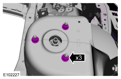