Ford Fiesta: Steering Column / Steering Wheel. Removal and Installation
Ford Fiesta 2014 - 2019 Service Manual / Steering System / Steering Column / Steering Wheel. Removal and Installation
Special Tool(s) / General Equipment
| Adhesive Tape |
Removal
NOTE: The removal steps in this procedure may include installation details.
-
Remove the driver airbag.
Refer to: Driver Airbag (501-20B Supplemental Restraint System, Removal and Installation).
-
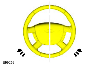
NOTE: Make sure that the road wheels are in the straight ahead position.
Position the road wheels in the straight ahead position.
 |
-
-
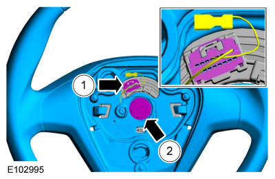
Disconnect the steering wheel electrical connector.
-
Remove the steering wheel bolt and the steering wheel.
Torque: 30 lb.ft (40 Nm)
-
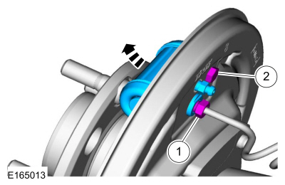
Disconnect the steering wheel electrical connector.
 |
-
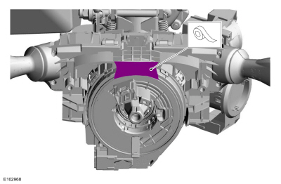
NOTICE: Make sure that the clockspring rotor does not rotate.
Tape the clockspring rotor to the outer housing to keep it from rotating.
Use the General Equipment: Adhesive Tape
 |
Installation
-
To install, reverse the removal procedure.
 Steering Column Shaft. Removal and Installation
Special Tool(s) /
General Equipment
Steering Wheel Holder
Removal
NOTE:
The removal steps in this procedure may include installation details...

Other information:
Ford Fiesta 2014 - 2019 Service Manual: Stoplamp Switch. Removal and Installation
Removal NOTE: Removal steps in this procedure may contain installation details. NOTICE: Do not press, pull or otherwise move the brake pedal while installing the stoplamp switch and cruise control deactivation switch. Install these switches with the booster push rod attached to the brake pedal and with the brake pedal in the at-rest position. Installing these switc..
Ford Fiesta 2014 - 2019 Service Manual: External Controls. Diagnosis and Testing
Principles of Operation Inspection and Verification Verify the customer concern. Visually inspect for obvious signs of mechanical damage. Make sure that the gearshift cables are correctly routed and not under any tension from other components. If an obvious cause for an observed or reported concern is found, correct the cause (if possi..
Categories
- Manuals Home
- Ford Fiesta Service Manual (2014 - 2019)
- Front Strut and Spring Assembly. Removal and Installation
- Maintenance Schedules
- Engine - 1.6L EcoBoost (132kW/180PS) – Sigma
- Fuel Pump. Removal and Installation
- Camshafts. Removal and Installation
Brake Backing Plate. Removal and Installation
Removal
NOTE: Removal steps in this procedure may contain installation details.
Remove the brake shoes.Refer to: Brake Shoes (206-02 Drum Brake, Removal and Installation).
Disconnect the brake tube fitting.
Torque: 159 lb.in (18 Nm) Remove the bolt and wheel cylinder.
Torque: 106 lb.in (12 Nm)
 Disconnect the brake shoe lever fitting and re
Copyright © 2026 www.fofiesta7.com