Ford Fiesta: Roof Opening Panel / Roof Opening Panel Motor. Removal and Installation
Ford Fiesta 2014 - 2019 Service Manual / Body and Paint / Roof Opening Panel / Roof Opening Panel Motor. Removal and Installation
Special Tool(s) / General Equipment
| Wooden Block | |
| Interior Trim Remover |
Removal
NOTE: Removal steps in this procedure may contain installation details.
-
Remove the A-pillar trim panel.
Refer to: A-Pillar Trim Panel (501-05 Interior Trim and Ornamentation, Removal and Installation).
-
Remove the B-pillar trim panel.
Refer to: B-Pillar Trim Panel (501-05 Interior Trim and Ornamentation, Removal and Installation).
-
On both sides.
Position aside the door weatherstrips.
 |
-
On both sides.
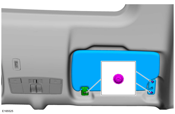
Remove the cover, the retainers and the sun visor.
 |
-
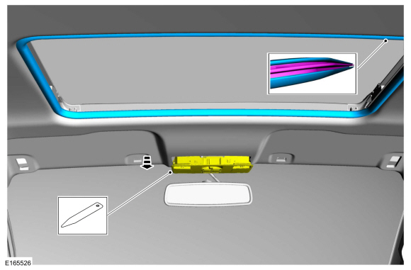
Position aside the dome lamp and remove the roof opening panel seal.
Use the General Equipment: Interior Trim Remover
 |
-
Remove the roof opening panel motor.
-
Lower the front of the headliner.
-
Insert the wooden blocks.
Use the General Equipment: Wooden Block
-
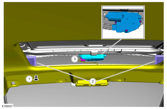
Disconnect the roof opening panel motor electrical
connector, remove the roof opening panel motor retainers and the roof
opening panel motor.
Torque: 27 lb.in (3 Nm)
-
Lower the front of the headliner.
 |
Installation
-
NOTE: When installing the roof opening panel motor, it may be necessary to turn the roof opening panel motor slightly to engage the drive splines.
To install, reverse the removal procedure
-
Initialize the roof opening panel.
Refer to: Power Roof Opening Panel Initialization (501-17 Roof Opening Panel, General Procedures).
 Roof Opening Panel Glass. Removal and Installation
Removal
NOTE:
Removal steps in this procedure may contain installation details.
NOTE:
The roof opening panel must be open to the vent position...
 Roof Opening Panel Shield. Removal and Installation
Removal
NOTE:
Removal steps in this procedure may contain installation details.
Remove the roof opening panel glass.
Refer to: Roof Opening Panel Glass (501-17 Roof Opening Panel, Removal and Installation)...
Other information:
Ford Fiesta 2014 - 2019 Service Manual: Center Register Air Discharge Temperature Sensor. Removal and Installation
Removal NOTE: Removal steps in this procedure may contain installation details. Release the clips and remove the instrument panel center upper trim panel. Disconnect the electrical connector and remove the center register air discharge temperature sensor...
Ford Fiesta 2014 - 2019 Service Manual: Rear Bumper Cover. Removal and Installation
Removal All vehicles NOTE: Removal steps in this procedure may contain installation details. NOTE: 5-door shown, 4-door is similar. With the vehicle in NEUTRAL, position it on a hoist. Refer to: Jacking and Lifting - Overview (100-02 Jacking and Lifting, Description and Operation)...
Categories
- Manuals Home
- Ford Fiesta Service Manual (2014 - 2019)
- Engine. Assembly
- Manual Transmission - 6-Speed Manual Transmission – B6
- Fuel Pump. Removal and Installation
- Engine
- Valve Cover. Removal and Installation
Component Bleeding. General Procedures
Special Tool(s) / General Equipment
Master Cylinder Bleeding SetBleeding
NOTICE: If the fluid is spilled on the paintwork, the affected area must be immediately washed down with cold water.
Master Cylinder
NOTE: When a new brake master cylinder has been installed, it should be primed to prevent air from entering the system.
NOTE: Make sure the area around the master cylinder cap is clean and free of foreign material.
Remove the brake fluid reservoir cap.Copyright © 2026 www.fofiesta7.com