Ford Fiesta: Glass, Frames and Mechanisms / Rear Door Window Glass. Removal and Installation
Ford Fiesta 2014 - 2019 Service Manual / Body and Paint / Glass, Frames and Mechanisms / Rear Door Window Glass. Removal and Installation
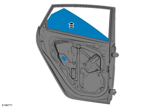
Removal
NOTE: LH shown, RH similar.
NOTE: Removal steps in this procedure may contain installation details.
All vehicles
-
Remove the rear door trim panel.
Refer to: Rear Door Trim Panel (501-05 Interior Trim and Ornamentation, Removal and Installation).
Vehicles with manual windows
-
Lower the rear door window glass.
-
Partially install the window crank handle.
-
Lower the rear door window glass.
-
Partially install the window crank handle.
 |
Vehicles with power windows
-
Lower the rear door window glass.
-
Connect the rear door window control switch.
-
Lower the rear door window glass.
-
Connect the rear door window control switch.
 |
All vehicles
-
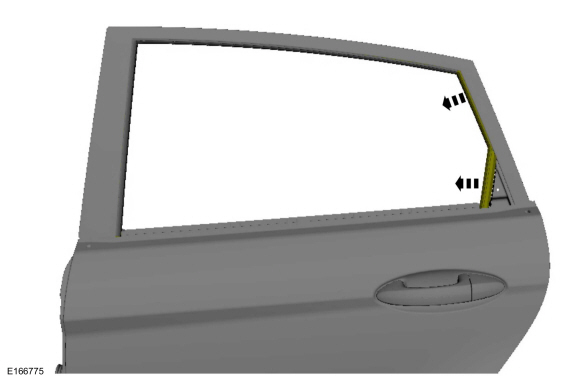
Remove and discard the outer belt moulding.
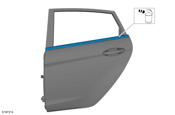 |
-
Remove the inner belt moulding.
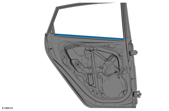 |
-
Position aside the rear door window top run.
 |
-
Remove the retainers and remove the aft rear door upper moulding.
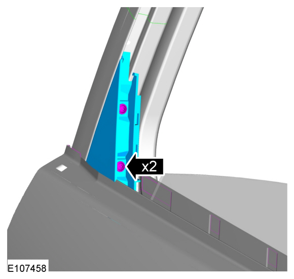 |
-
Remove the adhesive tape covers.
 |
Vehicles with manual windows
-
Install the rear door window crank handle and raise the rear door window glass to the half up position.
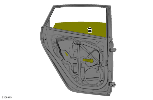 |
Vehicles with power windows
-
Install the rear door window control switch and raise the rear door window glass to the half up position.
 |
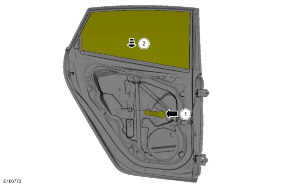
All vehicles
-
-
Remove the retainers.
Torque: 62 lb.in (7 Nm)
-
Rotate the rear door window glass 45 degrees clockwise.
-
Remove the retainers.
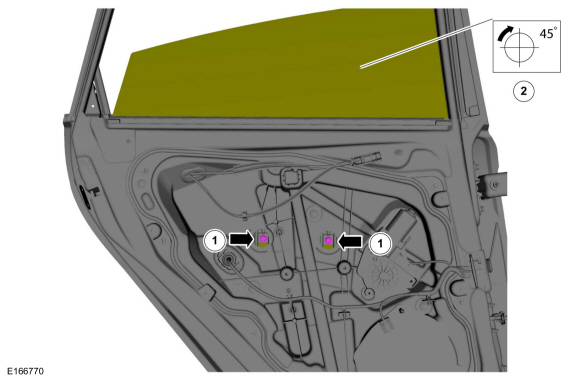 |
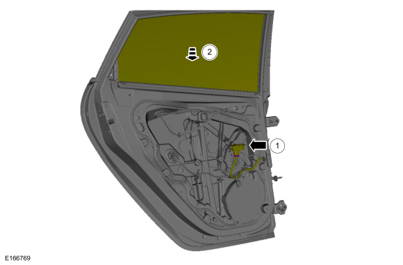
-
Remove the front door window glass.
 |
Installation
-
To install, reverse the removal procedure.
-
If the door is equipped with one touch up/down, carry out the power door window initialization.
Refer to: Power Door Window Initialization (501-11 Glass, Frames and Mechanisms, General Procedures).
 Front Door Glass Top Run. Removal and Installation
Removal
NOTE:
LH side shown, RH side similar.
Remove the front door window glass.
Refer to: Front Door Window Glass (501-11 Glass, Frames and Mechanisms, Removal and Installation)...
 Rear Door Window Regulator Motor. Removal and Installation
Removal
NOTE:
Removal steps in this procedure may contain installation details.
NOTE:
LH side shown, RH side similar.
Remove the rear door trim panel...
Other information:
Ford Fiesta 2014 - 2019 Service Manual: Electronic Engine Controls. Diagnosis and Testing
DTC Chart: Powertrain Control Module (PCM) Diagnostics in this manual assume a certain skill level and knowledge of Ford-specific diagnostic practices. Powertrain Control Module (PCM) DTC Chart DTC Description Action P0125 Insufficient Coolant Temp For Closed Loop Fuel Control ..
Ford Fiesta 2014 - 2019 Service Manual: Audio Unit Antenna. Removal and Installation
Removal NOTE: Removal steps in this procedure may contain installation details. Lower the headliner. Refer to: C-Pillar Upper Trim Panel - 4-Door (501-05 Interior Trim and Ornamentation, Removal and Installation). Refer to: Headliner - 5-Door (501-05 Interior Trim and Ornamentation, Removal and Installation). Remove the retainer, audio unit antenna a..
Categories
- Manuals Home
- Ford Fiesta Service Manual (2014 - 2019)
- Engine Cooling - 1.6L EcoBoost (132kW/180PS) – Sigma
- Fuel Pump. Removal and Installation
- Maintenance Schedules
- Front Strut and Spring Assembly. Removal and Installation
- Engine
Front Strut and Spring Assembly. Removal and Installation
Removal
NOTE: Removal steps in this procedure may contain installation details.
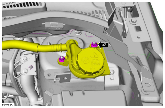
NOTE: This step is only necessary when installing a new component to the left-hand side.
Remove the nuts and position aside the remote brake fluid reservoir.Torque: 62 lb.in (7 Nm)
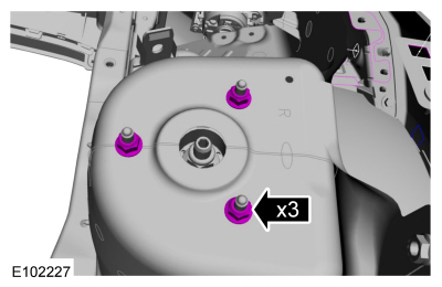
 Remove the strut and spring assembly upper mount nuts.
 Torque: 22 lb.ft (30 Nm)
Copyright © 2026 www.fofiesta7.com