Ford Fiesta: Handles, Locks, Latches and Entry Systems / Radio Frequency (RF) Receiver. Removal and Installation
Ford Fiesta 2014 - 2019 Service Manual / Body and Paint / Handles, Locks, Latches and Entry Systems / Radio Frequency (RF) Receiver. Removal and Installation
Special Tool(s) / General Equipment
| Interior Trim Remover |
Materials
| Name | Specification |
|---|---|
| 3M™ Super-Fast Repair Adhesive 04747 |
- |
Removal
-
Remove the headliner.
Refer to: Headliner - 5-Door (501-05 Interior Trim and Ornamentation, Removal and Installation).
Refer to: Headliner - 4-Door (501-05 Interior Trim and Ornamentation, Removal and Installation).
-
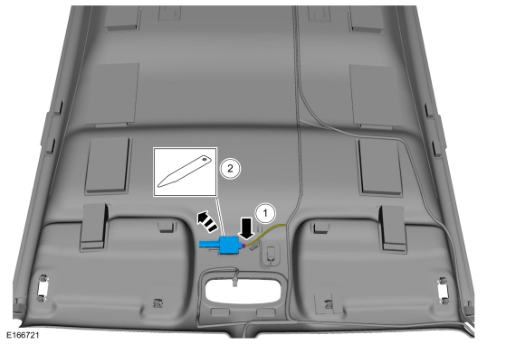
Remove the Radio Frequency (RF) receiver.
-
Disconnect the electrical connector.
-
Remove the Radio Frequency (RF) receiver.
Use the General Equipment: Interior Trim Remover
-
Disconnect the electrical connector.
 |
Installation
-
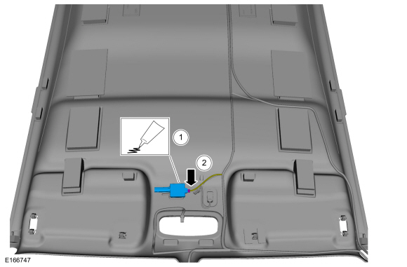
NOTE: The RFR module is secured to the headliner with 3M Duramix® 4747 Super Fast Adhesive at the assembly plant. When installing the RFR module, make sure to use 3M Duramix® 4747 Super Fast Adhesive to secure the RFR module to the headliner in approximately the same position and orientation on the headliner.
-
Install the Radio Frequency (RF) receiver.
Material: 3M™ Super-Fast Repair Adhesive / 04747
-
Connect the electrical connector.
-
Install the Radio Frequency (RF) receiver.
 |
-
Install the headliner.
Refer to: Headliner - 5-Door (501-05 Interior Trim and Ornamentation, Removal and Installation).
Refer to: Headliner - 4-Door (501-05 Interior Trim and Ornamentation, Removal and Installation).
 Liftgate Release Switch. Removal and Installation
Removal
Remove the luggage compartment lid moulding - 5 door.
Refer to: Luggage Compartment Lid Moulding - 5-Door (501-08 Exterior Trim and Ornamentation, Removal and Installation)...

Other information:
Ford Fiesta 2014 - 2019 Service Manual: Fuel System Pressure Release. General Procedures
Pressure release NOTE: The fuel pump relay fuse is located in the BJB , location F11. Remove the fuel pump relay fuse. NOTE: It may take up to several minutes before the engine stalls. Start the engine and allow it to idle until the engine stalls. Crank the engine an additional 20 seconds to make sure the fuel system pressure has bee..
Ford Fiesta 2014 - 2019 Service Manual: Starting System. Diagnosis and Testing
Inspection and Verification Diagnostics in this manual assume a certain skill level and knowledge of Ford-specific diagnostic practices. REFER to: Diagnostic Methods (100-00 General Information, Description and Operation). Verify the customer concern by operating the starting system. Before diagnosing or repairing the starting system inspect the following items: ..
Categories
- Manuals Home
- Ford Fiesta Service Manual (2014 - 2019)
- Maintenance Schedules
- Jacking and Lifting - Overview. Description and Operation
- Engine
- Timing Belt. Removal and Installation
- Engine Component View. Description and Operation
Brake Master Cylinder. Removal and Installation
Removal
NOTICE: If the fluid is spilled on the paintwork, the affected area must be immediately washed down with cold water.
NOTE: Removal steps in this procedure may contain installation details.
All vehicles
Remove the battery tray.Refer to: Battery Tray - 1.6L Duratec-16V Ti-VCT (88kW/120PS) – Sigma (414-01 Battery, Mounting and Cables, Removal and Installation).
Refer to: Battery Tray - 1.6L EcoBoost (132kW/180PS) – Sigma (414-01 Battery, Mounting and Cables, Removal and Installation).
Disconnect the vacuum tube from the brake booster and detach the routing clip.
Copyright © 2026 www.fofiesta7.com