Ford Fiesta: Parking Aid - Vehicles With: Parking Aid Camera / Parking Aid. Diagnosis and Testing
DTC Charts
BCM
DTC Chart
|
DTC
|
Description
|
Action
|
|
B1088:83
|
LIN Bus "B": Value of Signal Protection Calculation Incorrect
|
GO to Pinpoint Test F
|
|
B1088:88
|
LIN Bus "B": Bus Off
|
GO to Pinpoint Test F
|
|
B115E:08
|
Camera Module: Bus Signal/Message Failure
|
GO to Pinpoint Test A
|
|
B115E:49
|
Camera Module: Internal Electronic Failure
|
Sets in continuous memory when the BCM detects an internal fault in the
video camera. CLEAR the BCM Diagnostic Trouble Codes (DTCs) and test
the system for normal operation. If DTC B115E:49 returns, INSTALL a new
parking aid camera.
REFER to: Parking Aid Camera (413-13B Parking Aid - Vehicles With: Parking Aid Camera, Removal and Installation).
|
|
B115E:55
|
Camera Module: Not Configured
|
Sets in continuous memory when the BCM
detects that the video camera has not been configured. CONFIGURE the
camera using a diagnostic scan tool under Electrical>Service
Functions>LIN New Module Initialization.
|
|
U0264:87
|
Lost Communication With Camera Module- Rear: Missing Message
|
GO to Pinpoint Test F
|
|
All other Diagnostic Trouble Codes (DTCs)
|
—
|
REFER to: Body Control Module (BCM) (419-10 Multifunction Electronic Modules, Diagnosis and Testing).
|
APIM
DTC Chart
|
DTC
|
Description
|
Action
|
|
C1001:01
|
Vision System Camera: General Electrical Failure
|
GO to Pinpoint Test A
|
|
All other Diagnostic Trouble Codes (DTCs)
|
—
|
REFER to: Information and Entertainment System
(415-00B Information and Entertainment System - General Information -
Vehicles With: AM/FM/CD/SYNC/Touchscreen Display, Diagnosis and Testing).
|
Symptom Chart(s)
Symptom Chart: Parking Aid - Visual
|
Condition
|
Possible Sources
|
Action
|
|
The rear video camera system is inoperative or does not operate correctly
|
Refer to the Pinpoint Test
|
GO to Pinpoint Test A
|
|
The FDIM displays REAR VIDEO CAMERA IS UNAVAILABLE PLEASE CONTACT YOUR DEALERSHIP and a black screen/no image
|
Refer to the Pinpoint Test
|
GO to Pinpoint Test A
|
|
Static/flashing/blinking/flickering/scrolling or rolling
image/screen/scrolling horizontal lines
|
Refer to the Pinpoint Test
|
GO to Pinpoint Test B
|
|
Poor image quality
(foggy/cloudy/fuzzy/blurry/hazy image or moisture/water in lens or black
spots)
|
Refer to the Pinpoint Test
|
GO to Pinpoint Test B
|
|
Manual zoom function is inoperative
|
Refer to the Pinpoint Test
|
GO to Pinpoint Test E
|
|
Visual park aid alert is inoperative
|
Refer to the Pinpoint Test
|
GO to Pinpoint Test C
|
|
Fixed guidelines are inoperative or do not operate correctly
|
Refer to the Pinpoint Test
|
GO to Pinpoint Test D
|
|
Active guidelines are inoperative or do not operate correctly (if equipped)
|
Steering wheel is in straight-ahead position
|
Normal condition. Active guidelines are not shown unless steering wheel is rotated.
|
|
Refer to the Pinpoint Test
|
GO to Pinpoint Test D
|
|
Video camera delay feature is inoperative
|
Video camera delay feature is disabled
|
ENABLE the video camera delay feature within the APIM from the FDIM touchscreen display.
|
|
Refer to the Pinpoint Test
|
GO to Pinpoint Test D
|
|
Video image is upside down
|
Refer to the Pinpoint Test
|
GO to Pinpoint Test G
|
|
All other image concerns
|
Refer to the Pinpoint Test
|
GO to Pinpoint Test A
|
Pinpoint Tests
The Rear Video Camera System Is Inoperative or Does Not Operate Correctly
Refer to Wiring Diagrams Cell 131 for schematic and connector information.
Normal Operation and Fault Conditions
REFER to: Parking Aid - System Operation and Component Description
(413-13B Parking Aid - Vehicles With: Parking Aid Camera, Description
and Operation).
APIM
DTC Fault Trigger Conditions
|
DTC
|
Description
|
Fault Trigger Conditions
|
|
C1001:01
|
Vision System Camera: General Electrical Failure
|
Sets in continuous memory if no video signal
is detected from the rear video camera for 3 seconds or more when the
key is on and the gear selector is in reverse. Sets on-demand if no
video signal is detected from the rear video camera for 1 second or more
during the APIM self-test.
|
BCM
DTC Fault Trigger Conditions
|
DTC
|
Description
|
Fault Trigger Conditions
|
|
B115E:08
|
Camera Module: Bus Signal/Message Failure
|
A continuous DTC that sets in the BCM when the camera is reporting errors via the LIN .
|
Possible Sources
-
Fuse
-
Wiring, terminals or connectors
-
Video camera
-
APIM concern
-
FDIM concern
-
BCM
Visual Inspection and Diagnostic Pre-checks
For video camera feature concerns, verify the video camera feature in question is enabled.
PINPOINT TEST A: THE REAR VIDEO CAMERA IS INOPERATIVE OR DOES NOT OPERATE CORRECTLY
| A1 CHECK THE REVERSING LAMPS OPERATION |
-
While observing the reversing lamps, move the gear selector lever through the entire range.
Do the reversing lamps operate only when the gear selector is in reverse?
| No |
DIAGNOSE the reversing lamps.
REFER to: Reversing Lamps (417-01 Exterior Lighting, Diagnosis and Testing).
|
|
| A2 PERFORM A NETWORK TEST |
-
Using a diagnostic scan tool, perform a network test.
Do all modules pass the network test?
| No |
REFER to: Communications Network (418-00 Module Communications Network, Diagnosis and Testing).
|
|
| A3 CHECK THE DIAGNOSTIC TROUBLE CODES (DTCS) FROM THE BCM (BODY CONTROL MODULE)
SELF-TEST |
-
Using a diagnostic scan tool, perform the BCM self-test.
Are any Diagnostic Trouble Codes (DTCs) present?
| Yes |
For DTC B115E:08, GO to A9
For all other BCM Diagnostic Trouble Codes (DTCs), REFER to the BCM
DTC chart in this section.
|
|
| A4 CHECK THE DIAGNOSTIC TROUBLE CODES (DTCS) FROM THE IPC (INSTRUMENT PANEL CLUSTER)
SELF-TEST |
-
Using a diagnostic scan tool, perform the IPC self-test.
Are any Diagnostic Trouble Codes (DTCs) present?
| Yes |
REFER to: Instrumentation, Message Center and Warning Chimes
(413-01 Instrumentation, Message Center and Warning Chimes, Diagnosis
and Testing).
|
|
| A5 CHECK FOR DIAGNOSTIC TROUBLE CODES (DTCS) FROM THE ACCESSORY PROTOCOL INTERFACE MODULE (APIM) SELF-TEST |
-
Using a diagnostic scan tool, perform the APIM self-test.
Are any Diagnostic Trouble Codes (DTCs) present?
| Yes |
For DTC C1001:01, GO to A8
For all other APIM Diagnostic Trouble Codes (DTCs),
REFER to: Information and Entertainment System
(415-00B Information and Entertainment System - General Information -
Vehicles With: AM/FM/CD/SYNC/Touchscreen Display, Diagnosis and Testing).
|
|
| A6 CHECK AND CLEAN THE VIDEO CAMERA LENS |
-
Make sure the video camera lens is clean and clear of any debris.
-
Test the video camera system and verify the camera image.
Is the video camera concern still present?
| No |
The system is operating correctly at this time. The concern was caused by a dirty video camera lens.
|
|
| A7 CHECK THE IMAGE DISPLAY |
-
Observe the FDIM while placing the vehicle in reverse.
Does the FDIM switch to video camera mode and display REAR VIDEO CAMERA UNAVAILABLE PLEASE CONTACT YOUR DEALERSHIP?
| No |
DIAGNOSE the FDIM and APIM .
REFER to: Information and Entertainment System
(415-00B Information and Entertainment System - General Information -
Vehicles With: AM/FM/CD/SYNC/Touchscreen Display, Diagnosis and Testing).
|
|
| A8 CHECK THE VIDEO SIGNAL CIRCUIT INTEGRITY |
-
Measure:
Click to display connectors
|
Positive Lead
|
Measurement / Action
|
Negative Lead
|
|
C2383-14
|

|
C2383-15
|
Is the resistance between 74 and 106 ohms?
|
| A9 CHECK THE SUPPLY VOLTAGE TO THE VIDEO CAMERA |
-
Disconnect Video Camera C4357
.
-
Measure:
Click to display connectors
|
Positive Lead
|
Measurement / Action
|
Negative Lead
|
|
C4357-1
|

|
Ground
|
Is the voltage greater than 11 volts?
| No |
VERIFY that CJB
fuse 6 (10A) is OK. If OK, REPAIR the circuit. If not OK, REFER to the
Wiring Diagrams Manual to identify the possible causes of the circuit
short.
|
|
| A10 CHECK FOR GROUND TO THE VIDEO CAMERA |
-
Measure:
Click to display connectors
|
Positive Lead
|
Measurement / Action
|
Negative Lead
|
|
C4357-1
|
|
C4357-5
|
Is the voltage greater than 11 volts?
|
| A11 CHECK THE VIDEO SIGNAL CIRCUITS FOR A SHORT TO VOLTAGE |
-
Disconnect Video Camera C4357 if not previously disconnected.
-
Measure:
Click to display connectors
|
Positive Lead
|
Measurement / Action
|
Negative Lead
|
|
C4375-4
|
|
Ground
|
|
C4357-3
|
|
Ground
|
Is any voltage present?
| Yes |
REPAIR the affected circuit.
|
|
| A12 CHECK THE VIDEO SIGNAL CIRCUITS FOR A SHORT TO GROUND |
-
Measure:
Click to display connectors
|
Positive Lead
|
Measurement / Action
|
Negative Lead
|
|
C4357-4
|
|
Ground
|
|
C4357-3
|
|
Ground
|
Are the resistances greater than 10,000 ohms?
| No |
REPAIR the affected circuit.
|
|
| A13 CHECK THE VIDEO SIGNAL CIRCUITS FOR A SHORT TO VIDEO SHIELD |
-
Measure:
Click to display connectors
|
Positive Lead
|
Measurement / Action
|
Negative Lead
|
|
C4357-4
|
|
C4357-6
|
|
C4357-3
|
|
C4357-6
|
Are the resistances greater than 10,000 ohms?
| No |
REPAIR the affected circuit.
|
|
| A14 CHECK THE VIDEO SIGNAL CIRCUITS FOR A SHORT TO EACH OTHER |
-
Measure:
Click to display connectors
|
Positive Lead
|
Measurement / Action
|
Negative Lead
|
|
C4357-4
|
|
C4357-3
|
Is the resistance greater than 10,000 ohms?
| No |
REPAIR the affected circuit.
|
|
| A15 CHECK THE VIDEO CAMERA SIGNAL CIRCUITS FOR AN OPEN |
-
Measure:
Click to display connectors
|
Positive Lead
|
Measurement / Action
|
Negative Lead
|
|
C4357-3
|
|
C2383-15
|
|
C4357-4
|
|
C2383-14
|
Are the resistances less than 3 ohms?
| Yes |
If the vehicle is equipped with a manual transaxle, GO to A16
If the vehicle is equipped with an automatic transaxle, GO to A17
|
| No |
REPAIR the circuit in question.
|
|
| A16 CHECK THE REVERSE GEAR INPUT CIRCUIT FOR VOLTAGE AT THE BCM (BODY CONTROL MODULE)
|
-
Measure:
Click to display connectors
|
Positive Lead
|
Measurement / Action
|
Negative Lead
|
|
C2280D-7
|
|
Ground
|
Is the voltage greater than 11 volts?
|
| A17 CHECK FOR CORRECT VIDEO CAMERA OPERATION |
-
Disconnect and inspect the video camera connector.
-
Repair:
-
corrosion (install new connector or terminals – clean module pins)
-
damaged or bent pins – install new terminals/pins
-
pushed-out pins – install new pins as necessary
-
Reconnect all previously disconnected connectors. Make sure they seat and latch correctly.
-
Operate the system and determine if the concern is still present.
Is the concern still present?
| Yes |
CHECK OASIS for any applicable Technical Service Bulletins (TSBs). If a
TSB exists for this concern, DISCONTINUE this test and FOLLOW TSB
instructions. If no Technical Service Bulletins (TSBs) address this
concern, INSTALL a new rear video camera.
REFER to: Parking Aid Camera (413-13B Parking Aid - Vehicles With: Parking Aid Camera, Removal and Installation).
If the concern is still present after video camera replacement, GO to A18
|
| No |
The system is operating correctly at this time.
Concern may have been caused by a loose or corroded connector. ADDRESS
the root cause of any connector or pin issues.
|
|
| A18 CHECK FOR CORRECT BCM (BODY CONTROL MODULE)
OPERATION |
-
Disconnect and inspect the BCM connectors.
-
Repair:
-
corrosion (install new connector or terminals – clean module pins)
-
damaged or bent pins – install new terminals/pins
-
pushed-out pins – install new pins as necessary
-
Reconnect the BCM connectors. Make sure they seat and latch correctly.
-
Operate the system and determine if the concern is still present.
Is the concern still present?
| Yes |
CHECK OASIS for any applicable Technical Service Bulletins (TSBs). If a
TSB exists for this concern, DISCONTINUE this test and FOLLOW the TSB
instructions. If no Technical Service Bulletins (TSBs) address this
concern, INSTALL a new BCM .
REFER to: Body Control Module (BCM) (419-10 Multifunction Electronic Modules, Removal and Installation).
|
| No |
The system is operating correctly at this time.
Concern may have been caused by a loose or corroded connector. ADDRESS
the root cause of any connector or pin issues.
|
|
Poor Image Quality
Refer to Wiring Diagrams Cell 131 for schematic and connector information.
Normal Operation and Fault Conditions
REFER to: Parking Aid - System Operation and Component Description
(413-13B Parking Aid - Vehicles With: Parking Aid Camera, Description
and Operation).
Possible Sources
-
Wiring, terminals or connectors
-
Video camera
PINPOINT TEST B: POOR IMAGE QUALITY
| B1 CHECK AND CLEAN THE REAR VIDEO CAMERA LENS |
-
Make sure the rear video camera lens is clean and clear of any debris.
Is the video image concern still present?
| No |
The system is operating correctly at this time. The concern was caused by a dirty video camera lens.
|
|
| B2 CHECK THE VIDEO SIGNAL CIRCUIT INTEGRITY |
-
Measure:
Click to display connectors
|
Positive Lead
|
Measurement / Action
|
Negative Lead
|
|
C2383-14
|
|
C2383-15
|
Is the resistance between 74 and 106 ohms?
|
| B3 CHECK THE VIDEO CAMERA GROUND CIRCUIT FOR AN OPEN |
-
Disconnect Video Camera C4357
.
-
Measure:
Click to display connectors
|
Positive Lead
|
Measurement / Action
|
Negative Lead
|
|
C4357-5
|
|
Ground
|
Is the resistance less than 3 ohms?
|
| B4 CHECK THE VIDEO SIGNAL CIRCUITS FOR A SHORT TO GROUND |
-
Disconnect Video Camera C4357
.
-
Measure:
Click to display connectors
|
Positive Lead
|
Measurement / Action
|
Negative Lead
|
|
C4357-4
|
|
Ground
|
|
C4357-3
|
|
Ground
|
Is the resistance greater than 10,000 ohms?
| No |
REPAIR the affected circuit.
|
|
| B5 CHECK THE VIDEO SIGNAL CIRCUITS FOR A SHORT TO THE VIDEO SHIELD |
-
Measure:
Click to display connectors
|
Positive Lead
|
Measurement / Action
|
Negative Lead
|
|
C4357-4
|
|
C4357-6
|
|
C4357-3
|
|
C4357-6
|
Are the resistances greater than 10,000 ohms?
| No |
REPAIR the affected circuit.
|
|
| B6 CHECK VIDEO SIGNAL CIRCUITS FOR HIGH RESISTANCE |
-
Disconnect Video Camera C4357
.
-
Measure:
Click to display connectors
|
Positive Lead
|
Measurement / Action
|
Negative Lead
|
|
C4357-3
|
|
C2383-15
|
|
C4357-4
|
|
C2383-14
|
Are the resistances less than 3 ohms?
| No |
REPAIR the affected circuit.
|
|
| B7 CHECK VIDEO SIGNAL CIRCUITS FOR A SHORT TOGETHER |
-
Measure:
Click to display connectors
|
Positive Lead
|
Measurement / Action
|
Negative Lead
|
|
C4357-3
|
|
C4357-4
|
Is the resistance greater than 10,000 ohms?
| No |
REPAIR the affected circuit.
|
|
| B8 CHECK THE VIDEO SHIELD CIRCUIT FOR AN OPEN |
-
Disconnect In-line C212
.
-
Measure:
Click to display connectors
|
Positive Lead
|
Measurement / Action
|
Negative Lead
|
|
(male) C212-18
|
|
C4357-6
|
Is the resistance less than 3 ohms?
|
| B9 CHECK FOR CORRECT VIDEO CAMERA OPERATION |
-
Disconnect and inspect the video camera connector.
-
Repair:
-
corrosion (install new connector or terminals – clean module pins)
-
damaged or bent pins – install new terminals/pins
-
pushed-out pins – install new pins as necessary
-
Reconnect all previously disconnected connectors. Make sure they seat and latch correctly.
-
Operate the system and determine if the concern is still present.
Is the concern still present?
| Yes |
CHECK OASIS for any applicable Technical Service Bulletins (TSBs). If a
TSB exists for this concern, DISCONTINUE this test and FOLLOW the TSB
instructions. If no Technical Service Bulletins (TSBs) address this
concern, INSTALL a new video camera
REFER to: Parking Aid Camera (413-13B Parking Aid - Vehicles With: Parking Aid Camera, Removal and Installation).
|
| No |
The system is operating correctly at this time.
Concern may have been caused by a loose or corroded connector. ADDRESS
the root cause of any connector or pin issues.
|
|
The Visual Park Aid Alert Is Inoperative
Refer to Wiring Diagrams Cell 131 for schematic and connector information.
Normal Operation and Fault Conditions
See Visual Park Aid Alert.
REFER to: Parking Aid - System
Operation and Component Description (413-13B Parking Aid - Vehicles
With: Parking Aid Camera, Description and Operation).
Possible Sources
-
Video camera
-
BCM concern
-
Audible parking aid system concern
Visual Inspection and Diagnostic Pre-checks
Verify that the audible parking aid system is working properly and the visual park aid is enabled in the FDIM .
PINPOINT TEST C: THE VISUAL PARK AID ALERT IS INOPERATIVE
| C1 CHECK THE BCM (BODY CONTROL MODULE)
DIAGNOSTIC TROUBLE CODES (DTCS) |
-
Using a diagnostic scan tool, check the BCM Continuous Memory Diagnostic Trouble Codes (CMDTCs).
Are any Continuous Memory Diagnostic Trouble Codes (CMDTCs) present?
| Yes |
REFER to the BCM
DTC chart in this section.
|
|
| C2 CHECK FOR CORRECT VIDEO CAMERA OPERATION |
-
Disconnect and inspect the video camera connector.
-
Repair:
-
corrosion (install new connector or terminals – clean module pins)
-
damaged or bent pins – install new terminals/pins
-
pushed-out pins – install new pins as necessary
-
Reconnect the video camera connector. Make sure it seats and latches correctly.
-
Operate the system and determine if the concern is still present.
Is the concern still present?
| Yes |
CHECK OASIS for any applicable Technical Service Bulletins (TSBs). If a
TSB exists for this concern, DISCONTINUE this test and FOLLOW TSB
instructions. If no Technical Service Bulletins (TSBs) address this
concern, INSTALL a new video camera.
REFER to: Parking Aid Camera (413-13B Parking Aid - Vehicles With: Parking Aid Camera, Removal and Installation).
|
| No |
The system is operating correctly at this time.
Concern may have been caused by a loose or corroded connector. ADDRESS
the root cause of any connector or pin issues.
|
|
The Video Delay Or Guidelines Are Inoperative
Refer to Wiring Diagrams Cell 131 for schematic and connector information.
Normal Operation and Fault Conditions
REFER to: Parking Aid - System Operation and Component Description
(413-13B Parking Aid - Vehicles With: Parking Aid Camera, Description
and Operation).
Possible Sources
-
Video camera concern
-
APIM concern
-
BCM concern
-
Steering angle data concern
Visual Inspection and Diagnostic Pre-checks
-
Verify the luggage compartment lid is properly latched.
PINPOINT TEST D: THE VIDEO DELAY OR GUIDELINES ARE INOPERATIVE
| D1 VERIFY AND ENABLE THE INOPERATIVE REAR VIDEO CAMERA FEATURE |
-
Verify and enable the inoperative feature using the FDIM .
-
Test the system for normal operation.
Does the video camera feature operate correctly?
| Yes |
The rear video camera system is operating correctly
at this time. The concern was caused by the feature being disabled.
|
|
| D2 CHECK THE BCM (BODY CONTROL MODULE)
CONTINUOUS MEMORY DIAGNOSTIC TROUBLE CODES (CMDTCS) |
-
Using a diagnostic scan tool, check the BCM Continuous Memory Diagnostic Trouble Codes (CMDTCs).
Are any Diagnostic Trouble Codes (DTCs) present?
| Yes |
REFER to the BCM
DTC chart in this section.
|
|
| D3 PERFORM A NETWORK TEST |
-
Using a diagnostic scan tool, perform a network test.
Do all modules pass the network test?
| No |
REFER to: Communications Network (418-00 Module Communications Network, Diagnosis and Testing).
|
|
| D4 CHECK THE DIAGNOSTIC TROUBLE CODES (DTCS) FROM THE PSCM (POWER STEERING CONTROL MODULE)
SELF-TEST |
-
Using a diagnostic scan tool, perform the PSCM self-test.
Are any Diagnostic Trouble Codes (DTCs) retrieved?
| Yes |
REFER to: Power Steering (211-02 Power Steering, Diagnosis and Testing).
|
|
| D5 CHECK THE DIAGNOSTIC TROUBLE CODES (DTCS) FROM THE APIM (SYNC MODULE)
SELF-TEST |
-
Using a diagnostic scan tool, perform the APIM self-test.
Are any Diagnostic Trouble Codes (DTCs) retrieved?
| Yes |
For DTC C1001:01, GO to Pinpoint Test A
For all other APIM Diagnostic Trouble Codes,
REFER to: Information and Entertainment System
(415-00B Information and Entertainment System - General Information -
Vehicles With: AM/FM/CD/SYNC/Touchscreen Display, Diagnosis and Testing).
|
| No |
For a video camera delay concern, GO to D8
For a fixed or active (if equipped) guideline concern, GO to D6
|
|
| D6 CHECK THE LUGGAGE COMPARTMENT LID AJAR SWITCH STATUS PID (PARAMETER IDENTIFICATION)
|
-
Using a diagnostic scan tool, view the BCM Parameter Identifications (PIDs).
-
Monitor the DOOR_SW_LUGG PID while opening and closing the luggage compartment lid.
Does the PID agree with the luggage compartment lid position?
| No |
REFER to: Locks, Latches and Entry Systems (501-14 Handles, Locks, Latches and Entry Systems, Diagnosis and Testing).
|
|
| D7 ISOLATE THE VIDEO CAMERA |
-
Install a new video camera.
REFER to: Parking Aid Camera (413-13B Parking Aid - Vehicles With: Parking Aid Camera, Removal and Installation).
-
Test the system for normal operation.
Is the concern still present?
| No |
The concern was caused by an inoperative video camera.
|
|
| D8 CHECK FOR CORRECT ACCESSORY PROTOCOL INTERFACE MODULE (APIM) OPERATION |
-
Disconnect and inspect the APIM connector.
-
Repair:
-
corrosion (install new connector or terminals – clean module pins)
-
damaged or bent pins – install new terminals/pins
-
pushed-out pins – install new pins as necessary
-
Reconnect the APIM connector. Make sure it seats and latches correctly.
-
Operate the system and determine if the concern is still present.
Is the concern still present?
| Yes |
CHECK OASIS for any applicable Technical Service Bulletins (TSBs). If a
TSB exists for this concern, DISCONTINUE this test and FOLLOW TSB
instructions. If no Technical Service Bulletins (TSBs) address this
concern,
 COMPLETE THE FDRS GUIDED ROUTINE COMPLETE THE FDRS GUIDED ROUTINE |
- NOTE: This procedure must be completed using FDRS. Do not clear DTCs until the FDRS procedure has completed.
 To complete the diagnosis, navigate to the FDRS Guided Routine tab and carry out the procedure SYNC. To complete the diagnosis, navigate to the FDRS Guided Routine tab and carry out the procedure SYNC.

|
|
| No |
The system is operating correctly at this time.
Concern may have been caused by a loose or corroded connector. ADDRESS
the root cause of any connector or pin issues.
|
|
| D9 CHECK FOR CORRECT BCM (BODY CONTROL MODULE)
OPERATION |
-
Disconnect and inspect the BCM connectors.
-
Repair:
-
corrosion (install new connector or terminals – clean module pins)
-
damaged or bent pins – install new terminals/pins
-
pushed-out pins – install new pins as necessary
-
Reconnect the BCM connectors. Make sure they seat and latch correctly.
-
Operate the system and determine if the concern is still present.
Is the concern still present?
| Yes |
CHECK OASIS for any applicable Technical Service Bulletins (TSBs). If a
TSB exists for this concern, DISCONTINUE this test and FOLLOW the TSB
instructions. If no Technical Service Bulletins (TSBs) address this
concern, INSTALL a new BCM .
REFER to: Body Control Module (BCM) (419-10 Multifunction Electronic Modules, Removal and Installation).
|
| No |
The system is operating correctly at this time.
Concern may have been caused by a loose or corroded connector. ADDRESS
the root cause of any connector or pin issues.
|
|
Manual Zoom Feature Is Inoperative
Normal Operation and Fault Conditions
See Manual Zoom.
REFER to: Parking Aid - System Operation and
Component Description (413-13B Parking Aid - Vehicles With: Parking Aid
Camera, Description and Operation).
Possible Sources
-
Video camera concern
-
BCM concern
-
APIM concern
PINPOINT TEST E: MANUAL ZOOM FEATURE IS INOPERATIVE
| E1 CHECK THE BCM (BODY CONTROL MODULE)
CONTINUOUS MEMORY DIAGNOSTIC TROUBLE CODES (CMDTCS) |
-
Using a diagnostic scan tool, check the BCM Continuous Memory Diagnostic Trouble Codes (CMDTCs).
Are any Diagnostic Trouble Codes (DTCs) present?
| Yes |
REFER to the BCM
DTC chart in this section.
|
|
| E2 PERFORM A NETWORK TEST |
-
Using a diagnostic scan tool, perform a network test.
Do the BCM and APIM pass the network test?
| No |
REFER to: Communications Network (418-00 Module Communications Network, Diagnosis and Testing).
|
|
| E3 CHECK FOR DIAGNOSTIC TROUBLE CODES (DTCS) FROM THE ACCESSORY PROTOCOL INTERFACE MODULE (APIM) SELF-TEST |
-
Using a scan tool, perform the APIM self-test.
Are any Diagnostic Trouble Codes (DTCs) retrieved?
| Yes |
For DTC C1001:01, GO to Pinpoint Test A
For all other APIM Diagnostic Trouble Codes,
REFER to: Information and Entertainment System
(415-00B Information and Entertainment System - General Information -
Vehicles With: AM/FM/CD/SYNC/Touchscreen Display, Diagnosis and Testing).
|
|
| E4 CHECK FOR CORRECT VIDEO CAMERA OPERATION |
-
Disconnect and inspect the video camera connector.
-
Repair:
-
corrosion (install new connector or terminals – clean module pins)
-
damaged or bent pins – install new terminals/pins
-
pushed-out pins – install new pins as necessary
-
Reconnect the video camera connector. Make sure it seats and latches correctly.
-
Operate the system and determine if the concern is still present.
Is the concern still present?
| Yes |
CHECK OASIS for any applicable Technical Service Bulletins (TSBs). If a
TSB exists for this concern, DISCONTINUE this test and FOLLOW the TSB
instructions. If no Technical Service Bulletins (TSBs) address this
concern, INSTALL a new rear video camera.
REFER to: Parking Aid Camera (413-13B Parking Aid - Vehicles With: Parking Aid Camera, Removal and Installation).
|
| No |
The system is operating correctly at this time.
Concern may have been caused by a loose or corroded connector. ADDRESS
the root cause of any connector or pin issues.
|
|
B1088:83, B1088:88, U0264:87
Normal Operation and Fault Conditions
See LIN Communication.
REFER to: Parking Aid - System Operation
and Component Description (413-13B Parking Aid - Vehicles With: Parking
Aid Camera, Description and Operation).
BCM
DTC Fault Trigger Conditions
|
DTC
|
Description
|
Fault Trigger Conditions
|
|
B1088:83
|
LIN Bus "B": Value of Signal Protection Calculation Incorrect
|
Sets in continuous memory when the BCM detects that a message received
from the video camera does not match the associated checksum.
|
|
B1088:88
|
LIN Bus "B": Bus off
|
Sets in continuous memory when the BCM detects a short to voltage or a short to ground on the LIN communication circuit.
|
|
U0264:87
|
Lost Communication With Camera Module- Rear: Missing Message
|
Sets in continuous memory when the BCM cannot communicate with the camera for 2 seconds or more when the ignition is on.
|
Possible Sources
-
Wiring, terminals or connectors
-
Video camera
-
BCM
PINPOINT TEST F: B1088:83, B1088:88, U0264:87
| F1 CHECK THE BCM (BODY CONTROL MODULE)
FOR OTHER CAMERA DIAGNOSTIC TROUBLE CODES (DTCS) |
-
Using a diagnostic scan tool, check the BCM Diagnostic Trouble Codes (DTCs).
Is DTC B115E:08, B115E:49 or B115E:55 present?
| Yes |
REFER to the BCM
DTC chart in this section.
|
|
| F2 CHECK THE LIN (LOCAL INTERCONNECT NETWORK)
CIRCUIT FOR A SHORT TO VOLTAGE |
-
Disconnect Video Camera C4357
.
-
Measure:
Click to display connectors
|
Positive Lead
|
Measurement / Action
|
Negative Lead
|
|
C4357-2
|
|
Ground
|
Is any voltage present?
|
| F3 CHECK THE LIN (LOCAL INTERCONNECT NETWORK)
CIRCUIT FOR A SHORT TO GROUND |
-
Measure:
Click to display connectors
|
Positive Lead
|
Measurement / Action
|
Negative Lead
|
|
C4357-2
|
|
Ground
|
Is the resistance greater than 10,000 ohms?
|
| F4 CHECK THE LIN (LOCAL INTERCONNECT NETWORK)
CIRCUIT FOR AN OPEN |
-
Measure:
Click to display connectors
|
Positive Lead
|
Measurement / Action
|
Negative Lead
|
|
C4357-2
|
|
C2280G-24
|
Is the resistance less than 3 ohms?
|
| F5 CHECK FOR CORRECT VIDEO CAMERA OPERATION |
-
Inspect the video camera connector.
-
Repair:
-
corrosion (install new connector or terminals – clean module pins)
-
damaged or bent pins – install new terminals/pins
-
pushed-out pins – install new pins as necessary
-
Reconnect all previously disconnected connectors. Make sure they seat and latch correctly.
-
Operate the system and determine if the concern is still present.
Is the concern still present?
| Yes |
CHECK OASIS for any applicable Technical Service Bulletins (TSBs). If a
TSB exists for this concern, DISCONTINUE this test and FOLLOW the TSB
instructions. If no Technical Service Bulletins (TSBs) address this
concern, INSTALL a new video camera.
REFER to: Parking Aid Camera (413-13B Parking Aid - Vehicles With: Parking Aid Camera, Removal and Installation).
If the concern is still present after camera replacement, GO to F6
|
| No |
The system is operating correctly at this time.
Concern may have been caused by a loose or corroded connector. ADDRESS
the root cause of any connector or pin issues.
|
|
| F6 CHECK FOR CORRECT BCM (BODY CONTROL MODULE)
OPERATION |
-
Disconnect and inspect the BCM connectors.
-
Repair:
-
corrosion (install new connector or terminals – clean module pins)
-
damaged or bent pins – install new terminals/pins
-
pushed-out pins – install new pins as necessary
-
Reconnect the BCM connectors. Make sure they seat and latch correctly.
-
Operate the system and determine if the concern is still present.
Is the concern still present?
| Yes |
CHECK OASIS for any applicable Technical Service Bulletins (TSBs). If a
TSB exists for this concern, DISCONTINUE this test and FOLLOW the TSB
instructions. If no Technical Service Bulletins (TSBs) address this
concern, INSTALL a new BCM .
REFER to: Body Control Module (BCM) (419-10 Multifunction Electronic Modules, Removal and Installation).
|
| No |
The system is operating correctly at this time.
Concern may have been caused by a loose or corroded connector. ADDRESS
the root cause of any connector or pin issues.
|
|
The Rear Video Camera Image Is Displayed Upside Down
Normal Operation and Fault Conditions
REFER to: Parking Aid - System Operation and Component Description
(413-13B Parking Aid - Vehicles With: Parking Aid Camera, Description
and Operation).
Possible Sources
-
Video camera concern
-
BCM concern
PINPOINT TEST G: THE REAR VIDEO CAMERA IMAGE IS DISPLAYED UPSIDE DOWN
| G1 CHECK THE BCM (BODY CONTROL MODULE)
CONTINUOUS MEMORY DIAGNOSTIC TROUBLE CODES (CMDTCS) |
-
Using a diagnostic scan tool, check the BCM Continuous Memory Diagnostic Trouble Codes (CMDTCs).
Are any Diagnostic Trouble Codes (DTCs) present?
| Yes |
REFER to the BCM
DTC chart in this section.
|
|
| G2 VERIFY THE VIDEO CAMERA IS PROPERLY CONFIGURED |
-
Using a diagnostic scan tool, clear all Diagnostic Trouble Codes (DTCs).
Does the rear video camera image still appear upside down?
| Yes |
CHECK OASIS for any applicable Technical Service Bulletins (TSBs). If a
TSB exists for this concern, DISCONTINUE this test and FOLLOW the TSB
instructions. If no Technical Service Bulletins (TSBs) address this
concern, INSTALL a new rear video camera.
REFER to: Parking Aid Camera (413-13B Parking Aid - Vehicles With: Parking Aid Camera, Removal and Installation).
|
| No |
The
system is working properly at this time. The concern was caused by the
rear video camera configuration.
|
|
Removal
Remove the luggage compartment lid moulding.
Refer to: Luggage Compartment Lid Moulding - 4-Door (501-08 Exterior Trim and Ornamentation, Removal and Installation)...
Other information:
B00C5:11, B00C5:12, B00C5:13 and B00C5:1D
Refer to Wiring Diagrams Cell 46 for schematic and connector information.
Normal Operation and Fault Conditions
The RCM monitors the passenger seat position sensor circuits for the following faults:
Open circuit
Short to voltage
Short to ground
Current out of range
Faulted passenger se..
Removal
NOTE:
Removal steps in this procedure may contain installation details.
Release the hose clamp and disconnect the hose from the crankcase vent oil separator.
Disconnect the KS electrical connector.
NOTE:
Note the position of the component before removal. The KS must be..

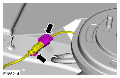
 Parking Aid Camera. Removal and Installation
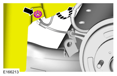 Disconnect the electrical connector and detach the wiring retainer.