Ford Fiesta: Suspension System - General Information / Front Toe Adjustment. General Procedures
Ford Fiesta 2014 - 2019 Service Manual / Suspension / Suspension System - General Information / Front Toe Adjustment. General Procedures
Special Tool(s) / General Equipment
| Wheel Alignment System |
Adjustment
-
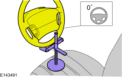
NOTE: Make sure that the vehicle is standing on a level surface.
 |
-
Using alignment equipment and the manufacturer's instructions, check the front toe setting on both sides.
Use the General Equipment: Wheel Alignment System
-
-
On both sides.
Torque: 58 lb.ft (79 Nm)
-
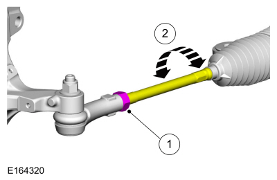
NOTE: Make sure that the boot is correctly located.
Rotate the inner tie-rods an equal amount in either a clockwise or a counterclockwise direction to adjust the toe setting on both sides.
-
On both sides.
 |
 Ride Height Measurement. General Procedures
Special Tool(s) /
General Equipment
Surface Gauge
Check
Ride Height Measurement - Front
NOTE:
Make sure that the vehicle is positioned on a flat,
level surface and the tires are inflated to the correct pressure...

Other information:
Ford Fiesta 2014 - 2019 Service Manual: Rear Door Window Control Switch. Removal and Installation
Removal NOTE: LH side shown, RH side similar. Remove the rear door window control switch. Remove the rear door window control switch from the door trim panel. Disconnect the rear door window control switch electrical connector. Installation To install, reverse the removal procedure. ..
Ford Fiesta 2014 - 2019 Service Manual: Universal Serial Bus (USB) Hub. Removal and Installation
Removal Open the floor console armrest. Remove the media hub. Disconnect the electrical connectors. Installation To install, reverse the removal procedure. ..
Categories
- Manuals Home
- Ford Fiesta Service Manual (2014 - 2019)
- Manual Transmission - 6-Speed Manual Transmission – B6
- Timing Belt. Removal and Installation
- Engine
- Front Suspension
- Camshafts. Removal and Installation
Brake Master Cylinder. Removal and Installation
Removal
NOTICE: If the fluid is spilled on the paintwork, the affected area must be immediately washed down with cold water.
NOTE: Removal steps in this procedure may contain installation details.
All vehicles
Remove the battery tray.Refer to: Battery Tray - 1.6L Duratec-16V Ti-VCT (88kW/120PS) – Sigma (414-01 Battery, Mounting and Cables, Removal and Installation).
Refer to: Battery Tray - 1.6L EcoBoost (132kW/180PS) – Sigma (414-01 Battery, Mounting and Cables, Removal and Installation).
Disconnect the vacuum tube from the brake booster and detach the routing clip.
Copyright © 2026 www.fofiesta7.com