Ford Fiesta: Instrument Panel and Interior Switches Illumination / Instrument Panel and Interior Switches Illumination. Diagnosis and Testing
DTC Chart: Body Control Module (BCM)
Diagnostics
in this manual assume a certain skill level and knowledge of
Ford-specific diagnostic practices. For information about these
practices,
REFER to: Diagnostic Methods (100-00 General Information, Description and Operation).
BCM
DTC Chart
|
DTC
|
Description
|
Action
|
|
B134E:13
|
Switch Illumination Adjustment Control: Circuit Open
|
GO to Pinpoint Test A
|
|
B134E:23
|
Switch Illumination Adjustment Control: Signal Stuck Low
|
GO to Pinpoint Test A
|
|
U2010:11
|
Switch Illumination Circuit Short To Ground
|
GO to Pinpoint Test B
|
DTC Chart: Front Control/Display Interface Module (FCDIM)
Diagnostics
in this manual assume a certain skill level and knowledge of
Ford-specific diagnostic practices. For information about these
practices,
REFER to: Diagnostic Methods (100-00 General Information, Description and Operation).
FCDIM
DTC Chart
|
DTC
|
Description
|
Action
|
|
U1A00:00
|
Private Communication Network: No Sub Type Information
|
-
For vehicles with AM/FM/CD:
REFER to: Information and Entertainment
System (415-00A Information and Entertainment System - General
Information - Vehicles With: AM/FM/CD/SYNC, Diagnosis and Testing).
-
For vehicle with AM/FM/CD SYNC:
REFER to: Information and
Entertainment System (415-00A Information and Entertainment System -
General Information - Vehicles With: AM/FM/CD/SYNC, Diagnosis and
Testing).
|
Symptom Chart(s)
Symptom Chart: Instrument Panel and Interior Switches Illumination
Diagnostics
in this manual assume a certain skill level and knowledge of
Ford-specific diagnostic practices. For information about these
practices,
REFER to: Diagnostic Methods (100-00 General Information, Description and Operation).
Symptom Chart
|
Condition
|
Possible Sources
|
Actions
|
|
A module does not respond to the diagnostic scan tool
|
-
Fuse
-
Wiring, terminals or connectors
-
Module
|
REFER to: Communications Network (418-00 Module Communications Network, Diagnosis and Testing).
|
|
All dimmable illumination (networked and
non-networked sources) does not dim or increase brightness
|
Refer to the Pinpoint Tests
|
GO to Pinpoint Test A
|
|
All dimmable non-networked illumination
is inoperative (networked illumination functions correctly)
|
Refer to the Pinpoint Tests
|
GO to Pinpoint Test B
|
|
All dimmable non-networked illumination
is always on (networked illumination functions correctly)
|
Refer to the Pinpoint Tests
|
GO to Pinpoint Test C
|
|
All dimmable networked illumination
(non-networked illumination functions correctly) does not dim
|
-
Network communication concern
-
BCM
|
-
Using a diagnostic scan tool, PERFORM a network test.
-
If the diagnostic scan tool responds with no communication to any module on the MS-CAN ,
REFER to: Communications Network (418-00 Module Communications Network, Diagnosis and Testing).
-
If the diagnostic scan tool communicates with the modules on the MS-CAN , INSTALL a new BCM .
REFER to: Body Control Module (BCM) (419-10 Multifunction Electronic Modules, Removal and Installation).
|
|
The steering wheel switch(es) illumination is inoperative
|
Refer to the Pinpoint Tests
|
GO to Pinpoint Test D
|
|
One or more switch or component illumination is inoperative
|
Refer to the Pinpoint Tests
|
GO to Pinpoint Test E
|
|
The start/stop switch illumination is
inoperative or always on (vehicles with push button start)
|
Refer to the Pinpoint Tests
|
GO to Pinpoint Test F
|
|
The window control switch illumination is inoperative
|
-
Wiring, terminals or connectors
-
Window control switch
|
-
VERIFY the operation of the power windows.
-
If the power windows operate correctly, INSTALL a new window control switch.
REFER to: Front Door Window Control Switch (501-11 Glass, Frames and Mechanisms, Removal and Installation).
REFER to: Rear Door Window Control Switch (501-11 Glass, Frames and Mechanisms, Removal and Installation).
-
If the power windows do not operate correctly,
REFER to: Glass,
Frames and Mechanisms - Vehicles With: Front Manual Windows (501-11
Glass, Frames and Mechanisms, Diagnosis and Testing).
|
|
The IPC illumination is inoperative/does not dim
|
-
Network communication concern
-
IPC
|
-
Using a diagnostic scan tool, PERFORM a network test.
-
If the IPC passes the network test,
 Click here to access Guided Routine (IPC).
-
If the diagnostic scan tool responds with no communication with the IPC ,
REFER to: Communications Network (418-00 Module Communications Network, Diagnosis and Testing).
|
|
The FCIM illumination is inoperative/does not dim (without touchscreen display)
|
Refer to the Pinpoint Tests
|
GO to Pinpoint Test G
|
|
The FCIM illumination is inoperative/does not dim (with touchscreen display)
|
-
Network communication concern
-
FCIM
|
-
VERIFY the operation of the audio system.
-
If the audio system operates correctly, INSTALL a new FCIM .
REFER to: Front Controls Interface Module (FCIM)
(415-00B Information and Entertainment System - General Information -
Vehicles With: AM/FM/CD/SYNC/Touchscreen Display, Removal and
Installation).
-
If the audio system does not operate correctly,
REFER to: Information and Entertainment System
(415-00B Information and Entertainment System - General Information -
Vehicles With: AM/FM/CD/SYNC/Touchscreen Display, Diagnosis and Testing).
|
|
The FCDIM illumination is inoperative/does not dim
|
-
Network communication concern
-
FCDIM
|
-
VERIFY the operation of the audio system.
-
If the audio system operates correctly, INSTALL a new FCDIM .
REFER
to: Front Control/Display Interface Module (FCDIM) (415-00A Information
and Entertainment System - General Information - Vehicles With:
AM/FM/CD/SYNC, Removal and Installation).
REFER to: Front Control/Display Interface Module (FCDIM) (415-00A
Information and Entertainment System - General Information - Vehicles
With: AM/FM/CD/SYNC, Removal and Installation).
-
If the audio system does not operate correctly,
REFER to:
Information and Entertainment System (415-00A Information and
Entertainment System - General Information - Vehicles With:
AM/FM/CD/SYNC, Diagnosis and Testing).
REFER to: Information and Entertainment System (415-00A Information and
Entertainment System - General Information - Vehicles With:
AM/FM/CD/SYNC, Diagnosis and Testing).
|
|
The FDIM illumination does not dim
|
-
Network communication concern
-
FDIM
|
PERFORM a network test. If the scan tool does not communicate with the APIM ,
REFER to: Communications Network (418-00 Module Communications Network, Diagnosis and Testing).
If the scan tool communicates with the APIM ,
 COMPLETE THE FDRS GUIDED ROUTINE COMPLETE THE FDRS GUIDED ROUTINE |
- NOTE: This procedure must be completed using FDRS. Do not clear DTCs until the FDRS procedure has completed.
To complete the diagnosis, navigate to the FDRS Guided Routine tab and carry out the procedure SYNC.

|
|
|
The HVAC illumination is inoperative/does not dim ( EMTC )
|
Refer to the Pinpoint Tests
|
GO to Pinpoint Test E
|
|
The HVAC illumination is inoperative/does not dim ( EATC )
|
-
Network communication concern
-
HVAC
|
-
Using a diagnostic scan tool, PERFORM a network test.
-
If the HVAC module passes the network test, INSTALL a new HVAC module.
REFER
to: Heating, Ventilation and Air Conditioning (HVAC) Control Module
(412-00 Climate Control System - General Information, Removal and
Installation).
-
If the HVAC module does not pass the network test,
REFER to: Communications Network (418-00 Module Communications Network, Diagnosis and Testing).
|
Pinpoint Tests
All Dimmable Illumination (Networked And Non-Networked Sources) Does Not Dim Or Increase Brightness
Refer to Wiring Diagrams Cell 71 for schematic and connector information.
Normal Operation and Fault Conditions
REFER to: Instrument Panel and Interior Switches Illumination -
System Operation and Component Description (413-00 Instrument Panel and
Interior Switches Illumination, Description and Operation).
DTC Fault Trigger Conditions
|
DTC
|
Description
|
Fault Trigger Conditions
|
|
B134E:13
|
Switch Illumination Adjustment Control: Circuit Open
|
A continuous and on-demand DTC that sets when the BCM detects the
instrument panel dimmer switch increase or decrease control circuits
open for more than 2 minutes.
|
|
B134E:23
|
Switch Illumination Adjustment Control: Signal Stuck low
|
A continuous and on-demand DTC that sets when the BCM
detects the instrument panel dimmer switch is stuck or held low for
more than 2 minutes or the increase or decrease control circuits are
shorted to ground.
|
Possible Sources
-
Wiring, terminals or connectors
-
Headlamp switch is OFF
-
Dimming set to AUTOMATIC in the FCDIM (if equipped)
-
Instrument panel dimmer switch
-
BCM
PINPOINT TEST A: ALL DIMMABLE ILLUMINATION (NETWORKED AND NON-NETWORKED SOURCES) DOES NOT DIM OR INCREASE BRIGHTNESS
| A1 PERFORM THE BCM (BODY CONTROL MODULE)
SELF-TEST |
-
Using a diagnostic scan tool, perform the BCM self-test.
Is DTC B134E:23 present?
|
| A2 CHECK VEHICLE EQUIPMENT |
-
Check if the vehicle is equipped with an FCDIM .
Is the vehicle equipped with an FCDIM ?
|
| A3 CHECK THE INSTRUMENT PANEL DIMMER SWITCH FOR A SHORT TO GROUND |
-
Disconnect Instrument Panel Dimmer Switch C2298
.
-
Using a diagnostic scan tool, clear the Diagnostic Trouble Codes (DTCs).
-
Repeat the BCM self-test.
Is on-demand DTC B134E:23 still present?
| No |
INSTALL a new instrument panel dimmer switch.
|
|
| A4 CHECK THE INSTRUMENT PANEL DIMMER SWITCH INPUT CIRCUITS FOR A SHORT TO GROUND |
-
Measure:
Click to display connectors
|
Positive Lead
|
Measurement / Action
|
Negative Lead
|
|
C2298-3
|

|
Ground
|
|
C2298-7
|
|
Ground
|
Are the resistances greater than 10,000 ohms?
| No |
REPAIR the circuit in question.
|
|
| A5 CHECK THE FCDIM (FRONT CONTROL/DISPLAY INTERFACE MODULE)
FOR A LIGHTING DIMMING MENU |
-
Using the LH upper steering wheel switch, verify if the FCDIM has a
lighting dimming menu. For additional information, REFER to the Owner's
Literature.
Does the FCDIM have a lighting dimming menu?
|
| A6 CHECK THE LIGHTING DIMMING SETTING IN THE FCDIM (FRONT CONTROL/DISPLAY INTERFACE MODULE)
|
-
Using the LH upper steering wheel switch, check the lighting dimming setting in the FCDIM .
Is the FCDIM lighting dimming setting set to automatic?
|
| A7 CHANGE THE LIGHTING DIMMING SETTING IN THE FCDIM (FRONT CONTROL/DISPLAY INTERFACE MODULE)
TO MANUAL |
-
Using the LH upper steering wheel switch, change the lighting dimming setting in the FCDIM from automatic to manual.
-
Place the headlamp switch in the PARKING LAMPS ON position.
-
Press the instrument panel dimmer switch up and down.
Do both networked and non-networked illumination sources increase and decrease in brightness?
| Yes |
The system is operating correctly at this time. The concern was caused by the dimming setting of the FCDIM .
|
|
| A8 CHECK THE INSTRUMENT PANEL DIMMER SWITCH |
-
Disconnect Instrument Panel Dimmer Switch C2298
.
-
For the illumination decrease function, connect and disconnect a fused jumper wire:
Click to display connectors
|
Lead 1
|
Measurement / Action
|
Lead 2
|
|
C2298-7
|

|
C2298-4
|
-
For the illumination increase function, connect and disconnect a fused jumper wire:
Click to display connectors
|
Lead 1
|
Measurement / Action
|
Lead 2
|
|
C2298-3
|
|
C2298-4
|
Does all dimmable illumination (networked and non-networked sources) dim or increase brightness?
| Yes |
INSTALL a new instrument panel dimmer switch.
|
|
| A9 CHECK THE INSTRUMENT PANEL DIMMER SWITCH GROUND CIRCUIT |
-
Connect:
Click to display connectors
|
Lead 1
|
Measurement / Action
|
Lead 2
|
|
C2298-4
|
|
Ground
|
Is the resistance less than 3 ohms?
| No |
REPAIR the ground circuit.
|
|
| A10 CHECK THE INSTRUMENT PANEL DIMMER SWITCH DIMMER UP AND DIMMER DOWN CIRCUITS FOR AN OPEN |
-
Measure:
Click to display connectors
|
Positive Lead
|
Measurement / Action
|
Negative Lead
|
|
C2298-3
|
|
C2280E-11
|
Click to display connectors
|
Positive Lead
|
Measurement / Action
|
Negative Lead
|
|
C2298-7
|
|
C2280F-12
|
Are the resistances less than 3 ohms?
| No |
REPAIR the circuit in question.
|
|
| A11 CHECK FOR CORRECT BCM (BODY CONTROL MODULE)
OPERATION |
-
Disconnect and inspect all BCM connectors.
-
Repair:
-
corrosion (install new connector or terminals – clean module pins)
-
damaged or bent pins - install new terminals/pins
-
pushed-out pins – install new pins as necessary
-
Reconnect the BCM connectors. Make sure they seat and latch correctly.
-
Operate the system and determine if the concern is still present.
Is the concern still present?
| Yes |
CHECK OASIS for any applicable Technical Service Bulletins (TSBs). If a
TSB exists for this concern, DISCONTINUE this test and FOLLOW the TSB
instructions. If no Technical Service Bulletins (TSBs) address this
concern, INSTALL a new BCM .
REFER to: Body Control Module (BCM) (419-10 Multifunction Electronic
Modules, Removal and Installation).
|
| No |
The system is operating correctly at this time. The
concern may have been caused by module connections. ADDRESS the root
cause of any connector or pin issues.
|
|
All Dimmable Non-Networked Illumination Is Inoperative (Networked Illumination Functions Correctly)
Refer to Wiring Diagrams Cell 71 for schematic and connector information.
Normal Operation and Fault Conditions
REFER to: Instrument Panel and Interior Switches Illumination -
System Operation and Component Description (413-00 Instrument Panel and
Interior Switches Illumination, Description and Operation).
DTC Fault Trigger Conditions
|
DTC
|
Description
|
Fault Trigger Conditions
|
|
U2010:11
|
Switch Illumination: Circuit Short To Ground
|
A continuous and on-demand DTC that sets when the BCM
has temporarily shut down the output driver. The module has
temporarily disabled the backlighting output because an excessive
current draw exists (such as a short to ground). The BCM
cannot enable the backlighting output until the cause of the short is
corrected, the Diagnostic Trouble Codes (DTCs) have been cleared and an
ignition cycle takes place.
|
Possible Sources
-
Wiring, terminals or connectors
-
BCM
PINPOINT TEST B: ALL DIMMABLE NON-NETWORKED ILLUMINATION IS INOPERATIVE (NETWORKED ILLUMINATION FUNCTIONS CORRECTLY)
| B1 VERIFY ALL NON-NETWORKED ILLUMINATION (EXCEPT THE START/STOP SWITCH [IF EQUIPPED]) IS INOPERATIVE |
-
Place the headlamp switch in the PARKING LAMPS ON position.
-
Press the instrument panel dimmer switch up and down.
Is the illumination for all non-networked switches and components (except the start/stop switch [if equipped]) inoperative?
|
| B2 CHECK ILLUMINATION FUNCTION WITH THE ILLUMINATION CIRCUIT JUMPERED |
-
Place the headlamp switch in the PARKING LAMPS OFF position.
-
NOTE:
If the jumper wire fuse fails during this step,
refer to the Wiring Diagrams manual to identify the possible causes of
the circuit short.
Connect:
Click to display connectors
|
Lead 1
|
Measurement / Action
|
Lead 2
|
|
Positive Battery Terminal
|
|
C2280E-24
|
Do the non-networked switches and components illuminate?
| Yes |
REMOVE the fused jumper wire. GO to B3
|
| No |
REMOVE the fused jumper wire. REPAIR the circuit.
|
|
| B3 CHECK FOR CORRECT BCM (BODY CONTROL MODULE)
OPERATION |
-
Disconnect and inspect all BCM connectors.
-
Repair:
-
corrosion (install new connector or terminals – clean module pins)
-
damaged or bent pins - install new terminals/pins
-
pushed-out pins – install new pins as necessary
-
Reconnect the BCM connectors. Make sure they seat and latch correctly.
-
Operate the system and determine if the concern is still present.
Is the concern still present?
| Yes |
CHECK OASIS for any applicable Technical Service Bulletins (TSBs). If a
TSB exists for this concern, DISCONTINUE this test and FOLLOW the TSB
instructions. If no TSBs address this concern, INSTALL a new BCM .
REFER to: Body Control Module (BCM) (419-10 Multifunction Electronic
Modules, Removal and Installation).
|
| No |
The system is operating correctly at this time. The
concern may have been caused by module connections. ADDRESS the root
cause of any connector or pin issues.
|
|
All Dimmable Non-Networked Illumination Is Always On (Networked Illumination Functions Correctly)
Refer to Wiring Diagrams Cell 71 for schematic and connector information.
Normal Operation and Fault Conditions
REFER to: Instrument Panel and Interior Switches Illumination -
System Operation and Component Description (413-00 Instrument Panel and
Interior Switches Illumination, Description and Operation).
Possible Sources
-
Wiring, terminals or connectors
-
BCM
PINPOINT TEST C: ALL DIMMABLE NON-NETWORKED ILLUMINATION IS ALWAYS ON (NETWORKED ILLUMINATION FUNCTIONS CORRECTLY)
| C1 CHECK THE EXTERIOR LIGHTING |
-
Place the headlamp switch in the OFF position.
-
Observe the parking lights.
Are the parking lights illuminated?
| Yes |
REFER to: Parking, Rear and License Plate Lamps (417-01 Exterior Lighting, Diagnosis and Testing).
|
|
| C2 CHECK THE BCM (BODY CONTROL MODULE)
BACKLIGHTING OUTPUT CIRCUIT FOR A SHORT TO VOLTAGE |
Do the dimmable backlighted components continue to illuminate?
|
| C3 CHECK FOR CORRECT BCM (BODY CONTROL MODULE)
OPERATION |
-
Disconnect and inspect all BCM connectors.
-
Repair:
-
corrosion (install new connector or terminals – clean module pins)
-
damaged or bent pins - install new terminals/pins
-
pushed-out pins – install new pins as necessary
-
Reconnect the BCM connectors. Make sure they seat and latch correctly.
-
Operate the system and determine if the concern is still present.
Is the concern still present?
| Yes |
CHECK OASIS for any applicable Technical Service Bulletins (TSBs). If a
TSB exists for this concern, DISCONTINUE this test and FOLLOW the TSB
instructions. If no TSB addresses this concern, INSTALL a new BCM .
REFER to: Body Control Module (BCM) (419-10 Multifunction Electronic
Modules, Removal and Installation).
|
| No |
The system is operating correctly at this time. The
concern may have been caused by module connections. ADDRESS the root
cause of any connector or pin issues.
|
|
The Steering Wheel Switch(es) Illumination Is Inoperative
Diagnostic Overview
Refer to Wiring Diagrams Cell 71 for schematic and connector information.
Normal Operation and Fault Conditions
REFER to: Instrument Panel and Interior Switches Illumination -
System Operation and Component Description (413-00 Instrument Panel and
Interior Switches Illumination, Description and Operation).
Possible Sources
-
Wiring, terminals or connectors
-
Steering wheel switch(es)
-
Clockspring
-
Steering wheel
PINPOINT TEST D: THE STEERING WHEEL SWITCH(ES) ILLUMINATION IS INOPERATIVE
| D1 INSPECT THE DIMMABLE NON-NETWORKED ILLUMINATION SOURCES |
-
Place the headlamp switch in the PARKING LAMPS ON position.
-
Place a shop light above the instrument panel ambient light sensor to make sure the BCM outputs maximum illumination voltage.
-
While pressing the instrument panel dimmer switch up
and down, monitor the dimmable non-networked illumination sources.
Are all of the dimmable non-networked illumination source inoperative or always on?
| Yes |
If all dimmable non-networked illumination sources are always on, GO to Pinpoint Test C
If all dimmable non-networked illumination sources are inoperative, GO to Pinpoint Test B
|
| No |
If all steering wheel switches illumination is inoperative, GO to D2
If the LH switch illumination is inoperative, GO to D6
If the RH switch illumination is inoperative, GO to D7
|
|
| D2 CHECK THE HORN OPERATION |
-
Press the airbag module against the steering wheel.
Does the horn sound?
| No |
REFER to: Horn (413-06 Horn, Diagnosis and Testing).
|
|
| D3 CHECK FOR ILLUMINATION VOLTAGE AND GROUND AT THE CLOCKSPRING |
-
Place the headlamp switch in the OFF position.
-
 WARNING:
Turn the ignition OFF and wait one minute to
deplete the backup power supply. Failure to follow this instruction may
result in serious personal injury or death in the event of an accidental
deployment.
Wait one minute.
WARNING:
Turn the ignition OFF and wait one minute to
deplete the backup power supply. Failure to follow this instruction may
result in serious personal injury or death in the event of an accidental
deployment.
Wait one minute.
-
Disconnect Clockspring C218B
.
-
Place the headlamp switch in the PARKING LAMPS ON position.
-
Press and hold the instrument panel dimmer switch up to the full illumination position.
-
Measure:
Click to display connectors
|
Positive Lead
|
Measurement / Action
|
Negative Lead
|
|
C218B-13
|

|
C218B-15
|
Is the voltage greater than 11 volts?
|
| D4 CHECK FOR ILLUMINATION VOLTAGE AT THE CLOCKSPRING |
-
Measure:
Click to display connectors
|
Positive Lead
|
Measurement / Action
|
Negative Lead
|
|
C218B-13
|
|
Ground
|
Is the voltage greater than 11 volts?
| Yes |
REPAIR the illumination ground circuit
|
| No |
REPAIR the illumination circuit.
|
|
| D5 CHECK FOR ILLUMINATION VOLTAGE AND GROUND TO THE STEERING WHEEL SWITCHES |
-
Place the headlamp switch in the OFF position.
-
Remove the driver airbag.
REFER to: Driver Airbag (501-20B Supplemental Restraint System, Removal and Installation).
-
Connect Clockspring C218B
.
-
Disconnect Clockspring C218C
.
-
Place the headlamp switch in the PARKING LAMPS ON position.
-
Measure:
Click to display connectors
|
Positive Lead
|
Measurement / Action
|
Negative Lead
|
|
C218C-7 (component side)
|
|
C218C-5 (component side)
|
Is the voltage greater than 11 volts?
| Yes |
INSTALL a new steering wheel.
REFER to: Steering Wheel (211-04 Steering Column, Removal and Installation).
|
| No |
INSTALL a new clockspring.
REFER to: Clockspring (501-20B Supplemental Restraint System, Removal and Installation).
|
|
| D6 CHECK THE LH (LEFT-HAND)
STEERING WHEEL SWITCH |
-
WARNING:
Turn the ignition OFF and wait one minute to
deplete the backup power supply. Failure to follow this instruction may
result in serious personal injury or death in the event of an accidental
deployment.
Wait one minute.
-
Remove the driver airbag.
REFER to: Driver Airbag (501-20B Supplemental Restraint System, Removal and Installation).
-
Disconnect
LH Steering Wheel Switch C2998
.
-
Measure:
Click to display connectors
|
Positive Lead
|
Measurement / Action
|
Negative Lead
|
|
C2998-3
|
|
C2998-1
|
Is the voltage greater than 11 volts?
| Yes |
INSTALL a new steering wheel switch.
REFER to: Steering Wheel Multifunction Switch (211-05 Steering Wheel
and Column Electrical Components, Removal and Installation).
|
| No |
INSTALL a new steering wheel.
REFER to: Steering Wheel (211-04 Steering Column, Removal and Installation).
|
|
| D7 CHECK THE RH (RIGHT-HAND)
STEERING WHEEL SWITCH |
-
WARNING:
Turn the ignition OFF and wait one minute to
deplete the backup power supply. Failure to follow this instruction may
result in serious personal injury or death in the event of an accidental
deployment.
Wait one minute.
-
Remove the driver airbag.
REFER to: Driver Airbag (501-20B Supplemental Restraint System, Removal and Installation).
-
Disconnect
RH Steering Wheel Switch C2999
.
-
Measure:
Click to display connectors
|
Positive Lead
|
Measurement / Action
|
Negative Lead
|
|
C2999-3
|
|
C2999-1
|
Is the voltage greater than 11 volts?
| Yes |
INSTALL a new steering wheel switch.
REFER to: Steering Wheel
Multifunction Switch (211-05 Steering Wheel and Column Electrical
Components, Removal and Installation).
|
| No |
INSTALL a new steering wheel.
REFER to: Steering Wheel (211-04 Steering Column, Removal and Installation).
|
|
One Or More Switch Or Component Illumination Is Inoperative
Refer to Wiring Diagrams Cell 71 for schematic and connector information.
Normal Operation and Fault Conditions
REFER to: Instrument Panel and Interior Switches Illumination -
System Operation and Component Description (413-00 Instrument Panel and
Interior Switches Illumination, Description and Operation).
Possible Sources
-
Wiring, terminals or connectors
-
Illuminated switch
-
Illuminated component
PINPOINT TEST E: ONE OR MORE SWITCH OR COMPONENT ILLUMINATION IS INOPERATIVE
| E1 CHECK THE VOLTAGE TO THE INDIVIDUAL ILLUMINATION SOURCE |
|
NOTE:
If the instrument panel dimmer switch illumination
is the inoperative source, increase the backlighting brightness to the
highest setting before disconnecting the instrument panel dimmer switch
connector.
-
Disconnect inoperative illumination source.
-
NOTE:
If the headlamp switch illumination is the
inoperative source, unplugging the headlamp switch connector causes the
BCM to turn the exterior lights on by default, so there is no need to
turn the parking lamps on.
Place the headlamp switch to the PARKING LAMPS ON position.
-
Press the dimmer switch up until the instrument panel illumination reaches full brightness.
-
Measure:
Instrument panel dimmer switch
|
Positive Lead
|
Measurement / Action
|
Negative Lead
|
|
C2298-2
|
|
Ground
|
Click to display connectors
Headlamp switch
|
Positive Lead
|
Measurement / Action
|
Negative Lead
|
|
C205-1
|
|
Ground
|
Click to display connectors
Driver heated seat switch
|
Positive Lead
|
Measurement / Action
|
Negative Lead
|
|
C2400-5
|
|
Ground
|
Click to display connectors
Passenger heated seat/ambient lighting switch
|
Positive Lead
|
Measurement / Action
|
Negative Lead
|
|
C2401-5
|
|
Ground
|
Click to display connectors
HVAC module ( EMTC )
|
Positive Lead
|
Measurement / Action
|
Negative Lead
|
|
C2357A-6
|
|
Ground
|
Click to display connectors
Selector Lever
|
Positive Lead
|
Measurement / Action
|
Negative Lead
|
|
C3245-4
|
|
Ground
|
Is the voltage greater than 11 volts?
| No |
REPAIR the circuit in question.
|
|
| E2 CHECK THE VOLTAGE TO THE INDIVIDUAL ILLUMINATION SOURCE USING THE CONNECTOR GROUND |
-
Measure:
Instrument panel dimmer switch
|
Positive Lead
|
Measurement / Action
|
Negative Lead
|
|
C2298-2
|
|
C2298-1
|
Click to display connectors
Headlamp switch
|
Positive Lead
|
Measurement / Action
|
Negative Lead
|
|
C205-1
|
|
C205-8
|
Click to display connectors
Driver heated seat switch
|
Positive Lead
|
Measurement / Action
|
Negative Lead
|
|
C2400-5
|
|
C2400-4
|
Click to display connectors
Passenger heated seat/ambient lighting switch
|
Positive Lead
|
Measurement / Action
|
Negative Lead
|
|
C2401-5
|
|
C2401-4
|
Click to display connectors
HVAC module ( EMTC )
|
Positive Lead
|
Measurement / Action
|
Negative Lead
|
|
C2357A-6
|
|
C2357A-13
|
Click to display connectors
Selector Lever
|
Positive Lead
|
Measurement / Action
|
Negative Lead
|
|
C3245-4
|
|
C3245-5
|
Is the voltage greater than 11 volts?
| Yes |
INSTALL a new component in question.
|
| No |
REPAIR the circuit in question.
|
|
The Start-Stop Switch Illumination Is Inoperative or Always On (vehicles with push button start)
Refer to Wiring Diagrams Cell 71 for schematic and connector information.
Refer to Wiring Diagrams Cell 20 for schematic and connector information.
Normal Operation and Fault Conditions
The BCM supply and control the start/stop switch illumination.
Possible Sources
-
Wiring, terminals or connectors
-
Start/stop switch
-
BCM
PINPOINT TEST F: THE START-STOP SWITCH ILLUMINATION IS INOPERATIVE OR ALWAYS ON (VEHICLES WITH PUSH BUTTON START)
| F1 VERIFY THE START-STOP SWITCH ILLUMINATION OPERATION |
-
Place the headlamp switch to the PARKING LAMPS ON position.
-
Press the dimmer switch up and down to change the level of the instrument panel illumination.
Is the start/stop switch illumination inoperative or always on?
| Yes |
If the start/stop switch illumination is inoperative, GO to F2
If the start/stop switch illumination is always on, GO to F4
|
| No |
The system is operating correctly at this time. The
concern may have been caused by component connections. ADDRESS the root
cause of any wiring, terminal or connector issues.
|
|
| F2 CHECK FOR ILLUMINATION VOLTAGE AND GROUND AT THE START/STOP SWITCH |
-
Disconnect Start/Stop Switch C2195
.
-
Press the dimmer switch up until the instrument panel illumination reaches full brightness.
-
Measure:
|
Positive Lead
|
Measurement / Action
|
Negative Lead
|
|
C2195-6
|
|
C2195-1
|
Is the voltage greater than 11 volts?
| Yes |
INSTALL a new start/stop switch.
REFER to: Ignition Switch -
Vehicles Without: Keyless Entry and Push Button Start (211-05 Steering
Wheel and Column Electrical Components, Removal and Installation).
|
|
| F3 CHECK FOR ILLUMINATION VOLTAGE AT THE START/STOP SWITCH |
-
Measure:
Click to display connectors
|
Positive Lead
|
Measurement / Action
|
Negative Lead
|
|
C2195-6
|
|
Ground
|
Is the voltage greater than 11 volts?
| Yes |
REPAIR the illumination ground circuit.
|
| No |
REPAIR the illumination circuit.
|
|
| F4 CHECK THE START/STOP SWITCH ILLUMINATION CIRCUIT FOR A SHORT TO VOLTAGE |
-
Disconnect Start/Stop Switch C2195
.
-
Measure:
Click to display connectors
|
Positive Lead
|
Measurement / Action
|
Negative Lead
|
|
C2195-6
|
|
Ground
|
Is any voltage present?
| Yes |
REPAIR the illumination circuit.
|
|
| F5 CHECK FOR CORRECT BCM (BODY CONTROL MODULE)
OPERATION |
-
Disconnect and inspect all BCM connectors.
-
Repair:
-
corrosion (install new connector or terminals – clean module pins)
-
damaged or bent pins - install new terminals/pins
-
pushed-out pins – install new pins as necessary
-
Reconnect all BCM connectors. Make sure they seat and latch correctly.
-
Operate the system and determine if the concern is still present.
Is the concern still present?
| Yes |
CHECK OASIS for any applicable Technical Service Bulletins (TSBs). If a
TSB exists for this concern, DISCONTINUE this test and FOLLOW the TSB
instructions. If no Technical Service Bulletins (TSBs) address this
concern, INSTALL a new BCM .
REFER to: Body Control Module (BCM) (419-10 Multifunction Electronic
Modules, Removal and Installation).
|
| No |
The system is operating correctly at this time. The
concern may have been caused by module connections. ADDRESS the root
cause of any connector or pin issues.
|
|
The FCIM Illumination Is Inoperative/Does Not Dim (Without Touchscreen Display)
Diagnostic Overview
Refer to Wiring Diagrams Cell 130 for schematic and connector information.
Normal Operation and Fault Conditions
REFER to: Instrument Panel and Interior Switches Illumination -
System Operation and Component Description (413-00 Instrument Panel and
Interior Switches Illumination, Description and Operation).
Possible Sources
-
Wiring, terminals or connectors
-
Network communication concern
-
LIN
-
FCIM
-
FCDIM
PINPOINT TEST G: THE FCIM (FRONT CONTROLS INTERFACE MODULE)
ILLUMINATION IS INOPERATIVE/DOES NOT DIM (WITHOUT TOUCHSCREEN DISPLAY)
| G1 PERFORM A NETWORK TEST |
-
Using a diagnostic scan tool, perform a network test.
Does the FCDIM pass the network test.
| No |
REFER to: Communications Network (418-00 Module Communications Network, Diagnosis and Testing).
|
|
| G2 CHECK THE FCDIM (FRONT CONTROL/DISPLAY INTERFACE MODULE)
CONTINUOUS MEMORY DIAGNOSTIC TROUBLE CODES (CMDTCS) |
-
Using a diagnostic scan tool, check the FCDIM Continuous Memory Diagnostic Trouble Codes (CMDTCS).
Are any Diagnostic Trouble Codes (DTCs) present?
| Yes |
REFER to: Information and Entertainment System (415-00A Information
and Entertainment System - General Information - Vehicles With:
AM/FM/CD/SYNC, Diagnosis and Testing).
REFER to: Information and Entertainment System (415-00A Information
and Entertainment System - General Information - Vehicles With:
AM/FM/CD/SYNC, Diagnosis and Testing).
|
|
| G3 CHECK THE VOLTAGE TO THE FCIM (FRONT CONTROLS INTERFACE MODULE)
|
-
Measure:
Click to display connectors
|
Positive Lead
|
Measurement / Action
|
Negative Lead
|
|
C2402-8
|
|
Ground
|
Is the voltage greater then 11 volts?
| No |
CHECK CJB
fuse 7 (7.5A). If the fuse is OK, REPAIR the circuit for an open. If
the fuse is not OK, REFER to the Wiring Diagram manual to identify the
possible cause of the circuit short.
|
|
| G4 CHECK FOR GROUND TO THE FCIM (FRONT CONTROLS INTERFACE MODULE)
|
-
Measure:
Click to display connectors
|
Positive Lead
|
Measurement / Action
|
Negative Lead
|
|
C2402-8
|
|
C2402-5
|
Is the voltage greater then 11 volts?
|
| G5 CHECK THE LIN (LOCAL INTERCONNECT NETWORK)
CIRCUIT FOR A SHORT TO VOLTAGE |
-
Measure:
Click to display connectors
|
Positive Lead
|
Measurement / Action
|
Negative Lead
|
|
C2402-7
|
|
Ground
|
Is any voltage present?
|
| G6 CHECK THE LIN (LOCAL INTERCONNECT NETWORK)
FOR A SHORT TO GROUND |
-
Measure:
Click to display connectors
|
Positive Lead
|
Measurement / Action
|
Negative Lead
|
|
C2402-7
|
|
Ground
|
Is the resistance greater than 10,000 ohms?
|
| G7 CHECK THE LIN (LOCAL INTERCONNECT NETWORK)
FOR AN OPEN |
-
Measure:
Click to display connectors
|
Positive Lead
|
Measurement / Action
|
Negative Lead
|
|
C2402-7
|
|
C2123-8
|
Is the resistance less than 3 ohms?
|
| G8 CHECK FOR CORRECT FCIM (FRONT CONTROLS INTERFACE MODULE)
OPERATION |
-
Disconnect and inspect the FCIM connector.
-
Repair:
-
corrosion (install new connector or terminals – clean module pins)
-
damaged or bent pins - install new terminals/pins
-
pushed-out pins – install new pins as necessary
-
Reconnect the FCIM connector. Make sure it seat and latch correctly.
-
Operate the system and determine if the concern is still present.
Is the concern still present?
| Yes |
CHECK OASIS for any applicable Technical Service Bulletins (TSBs). If a
TSB exists for this concern, DISCONTINUE this test and FOLLOW the TSB
instructions. If no Technical Service Bulletins (TSBs) address this
concern, INSTALL a new FCIM .
REFER to: Front Controls Interface Module (FCIM) (415-00A Information
and Entertainment System - General Information - Vehicles With:
AM/FM/CD/SYNC, Removal and Installation).
REFER to: Front Controls Interface Module (FCIM) (415-00A
Information and Entertainment System - General Information - Vehicles
With: AM/FM/CD/SYNC, Removal and Installation).
|
| No |
The system is operating correctly at this time. The
concern may have been caused by module connections. ADDRESS the root
cause of any connector or pin issues.
|
|
Other information:
B1404:11, B1404:12, B1404:13 and B1404:1A
Refer to Wiring Diagrams Cell 46 for schematic and connector information.
Normal Operation and Fault Conditions
The RCM continuously monitors the driver side airbag circuits for the following faults:
Resistance out of range
Unexpected voltage
Short to ground
Faulted driver side airbag
If a..
Special Tool(s) /
General Equipment
205-062Installer, Differential Bearing
Puller
Bearing Separator
Materials
Name
Specification
Motorcraft® Dual Clutch Transmission FluidXT-11-QDC
WSS-M2C200-D2
DISASSEMBLY
NOTICE:
Use vise jaw protectors.
Clamp the differential in a vise.
Remove th..


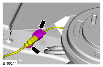
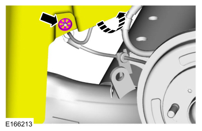 Disconnect the electrical connector and detach the wiring retainer.