Ford Fiesta: Anti-Lock Brake System (ABS) and Stability Control / Hydraulic Control Unit (HCU). Removal and Installation
Removal
NOTE: Removal steps in this procedure may contain installation details.
NOTE: The HCU and ABS module are serviced as an assembly.
-
NOTE: The PMI process must begin with the current ABS module installed. If the current ABS module does not respond to the diagnostic scan tool, the tool may prompt for As-Built Data as part of the repair.
If installing a new HCU / ABS module, using a diagnostic scan tool, begin the PMI process for the ABS module following the on-screen instructions.
-
With the vehicle in NEUTRAL, position it on a hoist.
Refer to: Jacking and Lifting - Overview (100-02 Jacking and Lifting, Description and Operation).
-
If equipped.
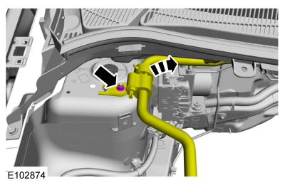
Remove the nut and position the evaporator outlet line bracket off of the stud.
Torque: 71 lb.in (8 Nm)
 |
-
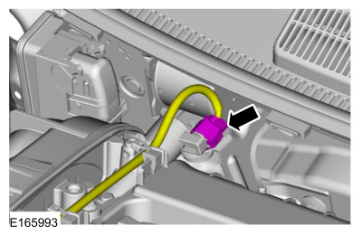
If equipped.
Disconnect the VCT oil control solenoid electrical connector.
 |
-
NOTICE: Make sure that all openings are sealed.
NOTICE: If the fluid is spilled on the paintwork, the affected area must be immediately washed down with cold water.
-
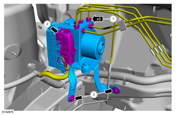
Disconnect the brake tube fittings.
Torque: 159 lb.in (18 Nm)
-
Disconnect the ABS module electrical connector.
-
Remove the bolts and HCU .
Torque: 17 lb.ft (23 Nm)
-
Disconnect the brake tube fittings.
 |
-
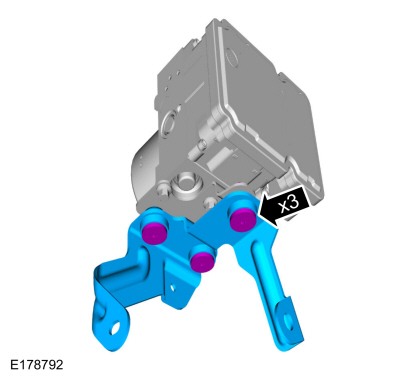
Remove the bolts and the HCU body bracket.
Torque: 80 lb.in (9 Nm)
 |
-
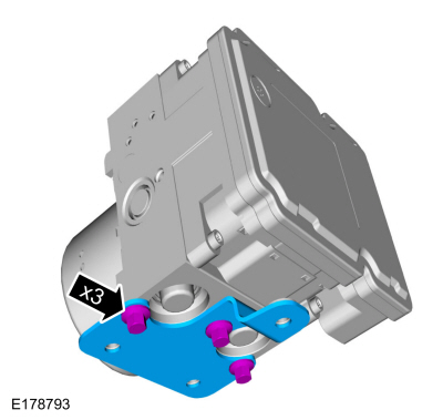
Remove the bolts and the HCU bracket.
Torque: 80 lb.in (9 Nm)
 |
Installation
-
To install, reverse the removal procedure.
-
Bleed the brake system.
Refer to: Brake System Pressure Bleeding (206-00 Brake System - General Information, General Procedures).
-
If a new HCU / ABS module was installed, using a diagnostic scan tool,
complete the PMI process for the ABS module following the on-screen
instructions.
 Brake Pedal Position (BPP) Switch Adjustment. General Procedures
Adjustment
NOTICE:
Do not press the brake pedal when installing or removing the
brake pedal position switch or damage to the brake pedal-mounted
switches can occur...
 Front Wheel Speed Sensor. Removal and Installation
Removal
NOTE:
Removal steps in this procedure may contain installation details.
Remove the wheel and tire.
Refer to: Wheel and Tire (204-04A Wheels and Tires, Removal and Installation)...
Other information:
Ford Fiesta 2014 - 2019 Service Manual: Battery Charging. General Procedures
Charging WARNING: Before beginning any service procedure in this section, refer to Safety Warnings in section 100-00 General Information. Failure to follow this instruction may result in serious personal injury. NOTE: Batteries will discharge due to normal parasitic key off-loads when the vehicle is on a dealer lot or parked by the customer for an extended period of..
Ford Fiesta 2014 - 2019 Service Manual: Climate Control System - Vehicles With: Electronic Automatic Temperature Control (EATC) - Overview. Description and Operation
Overview The climate control system consists of the following components: A/C compressor A/C compressor clutch assembly A/C condenser core A/C evaporator core Receiver/drier Connecting refrigerant lines Thermostatic Expansion Valve (TXV) Heater core and evaporator core housing HVAC control module ..
Categories
- Manuals Home
- Ford Fiesta Service Manual (2014 - 2019)
- Jacking and Lifting - Overview. Description and Operation
- Clutch - 6-Speed Manual Transmission – B6
- Manual Transmission - 6-Speed Manual Transmission – B6
- Maintenance Schedules
- Engine System - General Information
Brake Master Cylinder. Removal and Installation
Removal
NOTICE: If the fluid is spilled on the paintwork, the affected area must be immediately washed down with cold water.
NOTE: Removal steps in this procedure may contain installation details.
All vehicles
Remove the battery tray.Refer to: Battery Tray - 1.6L Duratec-16V Ti-VCT (88kW/120PS) – Sigma (414-01 Battery, Mounting and Cables, Removal and Installation).
Refer to: Battery Tray - 1.6L EcoBoost (132kW/180PS) – Sigma (414-01 Battery, Mounting and Cables, Removal and Installation).
Disconnect the vacuum tube from the brake booster and detach the routing clip.