Ford Fiesta: Anti-Lock Brake System (ABS) and Stability Control / Brake Pedal Position (BPP) Switch Adjustment. General Procedures
Ford Fiesta 2014 - 2019 Service Manual / Brake System / Anti-Lock Brake System (ABS) and Stability Control / Brake Pedal Position (BPP) Switch Adjustment. General Procedures
Adjustment
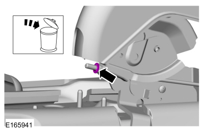
NOTICE: Do not press the brake pedal when installing or removing the brake pedal position switch or damage to the brake pedal-mounted switches can occur.
-
Inspect all brake pedal position switches and brake
pedal assembly to verify there is no brake pedal pressure
unintentionally applied due to incorrect brake pedal position switch or
brake pedal installation. Correct any concerns before proceeding to the
next step.
-
Remove the driver knee airbag.
Refer to: Driver Knee Airbag (501-20B Supplemental Restraint System, Removal and Installation).
-
Confirm that all brake pedal and bracket assembly fasteners are correctly tightened.
-
Install the driver knee airbag.
Refer to: Driver Knee Airbag (501-20B Supplemental Restraint System, Removal and Installation).
-
Using the Integrated Diagnostic System (IDS) scan tool,
select DataLogger->Chassis->Braking->Brake Switch Parameters.
-
NOTE: Using the scan tool record function makes it easier to observe the brake pressure sensor readings.
Set the ignition to ON.
-
Slowly apply the brake pedal to generate the pressure graph for the BPS
(brake pressure sensor) PID . The rate of brake pedal apply must not
exceed 5 psi per second as indicated by the scan tool.
-
Record the initial value of the BPS PID when BRAKE_LAMP and CRUISE_CANCL change from OFF to ON.
-
If BRAKE_LAMP and CRUISE_CANCL transition to ON before the BPS PID
reads 44 psi or less, the brake pedal position switch is correctly
installed.
-
If BRAKE_LAMP and CRUISE_CANCL transition to ON after the BPS PID
reads greater than 44 psi, replace the stoplamp switch and cruise
control deactivation switch (if equipped). Clear all Diagnostic Trouble
Codes (DTCs) and repeat Steps 3-6 to verify that the BRAKE_LAMP and
CRUISE_CANCL transition to ON before the BPS PID reads 44 psi or less.
 Anti-Lock Brake System (ABS) and Stability Control. Diagnosis and Testing
DTC Charts
DTC Chart: Anti-Lock Brake System (ABS) Module
Diagnostics in this manual assume a certain skill level and knowledge of Ford-specific diagnostic practices...
 Hydraulic Control Unit (HCU). Removal and Installation
Removal
NOTE:
Removal steps in this procedure may contain installation details.
NOTE:
The HCU and ABS module are serviced as an assembly.
NOTE:
The PMI process must begin with the current ABS module installed...
Other information:
Ford Fiesta 2014 - 2019 Service Manual: Instrument Panel Lower Trim Panel. Removal and Installation
Removal NOTE: Automatic transmission shown, manual transmission similar. Remove the selector lever finish panel. Release the clips and remove the instrument panel lower trim panel...
Ford Fiesta 2014 - 2019 Service Manual: Headliner - 5-Door. Removal and Installation
Materials Name Specification 3M™ Super-Fast Repair Adhesive04747 - Removal On both sides. Remove the retainers and the sun visor. On both sides. Remove the retainer and the sun visor clip...
Categories
- Manuals Home
- Ford Fiesta Service Manual (2014 - 2019)
- Timing Belt. Removal and Installation
- Manual Transmission, Clutch, Transfer Case and Power Transfer Unit
- Engine - 1.6L EcoBoost (132kW/180PS) – Sigma
- Maintenance Schedules
- Engine System - General Information
Parking Brake Control. Removal and Installation
Removal
NOTE: Removal steps in this procedure may contain installation details.
Remove the floor console.Refer to: Floor Console (501-12 Instrument Panel and Console, Removal and Installation).
Remove the driver seat.
Refer to: Front Seat (501-10 Seating, Removal and Installation).
Remove the parking brake cable adjustment lock nut.
 Loosen the parking brake cable adjustment nut.
Copyright © 2026 www.fofiesta7.com