
Ford Fiesta: Seating / Front Seat. Removal and Installation
Removal
 WARNING:
The following procedure describes critical repair steps
required for correct seat component installation. Follow all notes and
steps carefully. Do not place any objects between the seat components
and the body of the vehicle, nor any objects within a joint internal to
the seat structure. Failure to follow step instructions may result in
incorrect operation of the seat components and increases the risk of
serious personal injury.
WARNING:
The following procedure describes critical repair steps
required for correct seat component installation. Follow all notes and
steps carefully. Do not place any objects between the seat components
and the body of the vehicle, nor any objects within a joint internal to
the seat structure. Failure to follow step instructions may result in
incorrect operation of the seat components and increases the risk of
serious personal injury.
-
Depower the SRS .
Refer to: Supplemental Restraint System (SRS) Depowering and Repowering (501-20B Supplemental Restraint System, General Procedures).
-
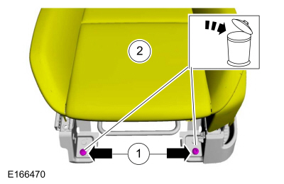
NOTE: Follow the unique instruction or graphic for this step in the installation.
Position the seat rearward. Remove and discard the seat track bolts.
 |
-
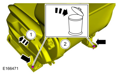
NOTE: Follow the unique instruction or graphic for this step in the installation.
Position the seat forward. Remove and discard the seat track bolts.
 |
-
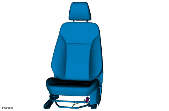
Disconnect the front seat electrical connector and remove the front seat.
 |
Installation
-
To install, reverse the removal procedure.
-
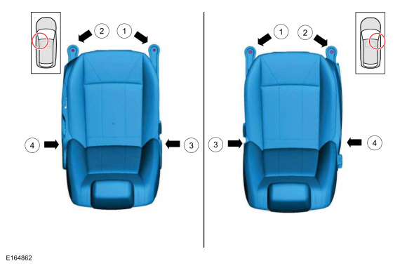
Install the front seat bolts in the following sequence.
-
Install the front inboard bolt.
Torque: 26 lb.ft (35 Nm)
-
Install the front outboard bolt.
Torque: 26 lb.ft (35 Nm)
-
Install the rear inboard bolt.
Torque: 26 lb.ft (35 Nm)
-
Install the rear outboard bolt.
Torque: 26 lb.ft (35 Nm)
-
Install the front inboard bolt.
 |
-
Repower the SRS .
Refer to: Supplemental Restraint System (SRS) Depowering and Repowering (501-20B Supplemental Restraint System, General Procedures).
 Seats. Diagnosis and Testing
DTC Chart: BCM
Diagnostics in this manual assume a certain skill level and knowledge of Ford-specific diagnostic practices. REFER to: Diagnostic Methods (100-00 General Information, Description and Operation)...
 Front Seat Backrest Cover. Removal and Installation
Special Tool(s) /
General Equipment
Flat Headed Screw Driver
Hog Ring Plier
Removal
WARNING:
Front seat backrest trim covers installed on seats equipped
with seat side airbags cannot be repaired...
Other information:
Ford Fiesta 2014 - 2019 Service Manual: Wheel and Tire. Disassembly and Assembly
Special Tool(s) / General Equipment Wooden Block DISASSEMBLY NOTICE: Failure to follow the instructions below may result in damage to the TPMS sensor. NOTICE: The TPMS sensor is mounted to the valve stem. Removal of the valve stem requires dismounting the tire from the wheel and removal of the TPMS sensor...
Ford Fiesta 2014 - 2019 Service Manual: Heated Oxygen Sensor (HO2S). Removal and Installation
Special Tool(s) / General Equipment 303-476 (T94P-9472-A) Socket, Exhaust Gas Oxygen SensorTKIT-1994-LM/MTKIT-1994-FTKIT-1994-FLM/FM Materials Name Specification Motorcraft® High Temperature Nickel Anti-Seize LubricantXL-2 - Motorcraft® Penetrating and Lock LubricantXL-1 - Removal Remove the air cleaner ..
Categories
- Manuals Home
- Ford Fiesta Service Manual (2014 - 2019)
- Service Information
- Front Suspension
- Maintenance Schedules
- Cylinder Head. Removal and Installation
- Engine. Assembly
Brake Master Cylinder. Removal and Installation
Removal
NOTICE: If the fluid is spilled on the paintwork, the affected area must be immediately washed down with cold water.
NOTE: Removal steps in this procedure may contain installation details.
All vehicles
Remove the battery tray.Refer to: Battery Tray - 1.6L Duratec-16V Ti-VCT (88kW/120PS) – Sigma (414-01 Battery, Mounting and Cables, Removal and Installation).
Refer to: Battery Tray - 1.6L EcoBoost (132kW/180PS) – Sigma (414-01 Battery, Mounting and Cables, Removal and Installation).
Disconnect the vacuum tube from the brake booster and detach the routing clip.
