Ford Fiesta: Seating / Seats. Diagnosis and Testing
DTC Chart: BCM
Diagnostics in this manual assume a certain skill level and knowledge of Ford-specific diagnostic practices.
REFER to: Diagnostic Methods (100-00 General Information, Description and Operation).
BCM
DTC Chart
|
DTC
|
Description
|
Action
|
|
B1034:12
|
Left Front Seat Heater Element: Circuit Short To Battery
|
GO to Pinpoint Test B
|
|
B1034:14
|
Left Front Seat Heater Element: Circuit Short To Ground or Open
|
If the heated seat is inoperative, GO to Pinpoint Test B If the heated seat is on all of the time, GO to Pinpoint Test D
|
|
B1036:12
|
Right Front Seat Heater Element: Circuit Short To Battery
|
GO to Pinpoint Test C
|
|
B1036:14
|
Right Front Seat Heater Element: Circuit Short To Ground or Open
|
If the heated seat is inoperative, GO to Pinpoint Test C If the heated seat is on all of the time, GO to Pinpoint Test D
|
|
B115A:23
|
Front Passenger Seat Heater: Signal Stuck Low
|
GO to Pinpoint Test C
|
|
B115B:23
|
Front Driver Seat Heater: Signal Stuck Low
|
GO to Pinpoint Test B
|
|
All other Diagnostic Trouble Codes (DTCs)
|
-
|
REFER to: Body Control Module (BCM) (419-10 Multifunction Electronic Modules, Diagnosis and Testing).
|
Symptom Chart(s)
Symptom Chart: Seating
Diagnostics in this manual assume a certain skill level and knowledge of Ford-specific diagnostic practices.
REFER to: Diagnostic Methods (100-00 General Information, Description and Operation).
Symptom Chart
|
Condition
|
Possible Sources
|
Actions
|
|
The heated seats are both inoperative — driver and passenger
|
Refer to the Pinpoint Test
|
GO to Pinpoint Test A
|
|
The heated seat is inoperative/does not operate correctly — driver
|
Refer to the Pinpoint Test
|
GO to Pinpoint Test B
|
|
The heated seat is inoperative/does not operate correctly — passenger
|
Refer to the Pinpoint Test
|
GO to Pinpoint Test C
|
|
The heated seat does not operate
correctly — driver or passenger seat heats when the system is off
|
Refer to the Pinpoint Test
|
GO to Pinpoint Test D
|
|
The heated seat does not operate
correctly — driver seat does heat but the heated seat indicator does not
illuminate when pressed
|
Refer to the Pinpoint Test
|
GO to Pinpoint Test E
|
|
The heated seat does not operate
correctly — passenger seat does heat but the heated seat indicator does
not illuminate when pressed
|
Refer to the Pinpoint Test
|
GO to Pinpoint Test F
|
|
The heated seat does not operate
correctly — driver or passenger heated seat indicator is always on
|
Refer to the Pinpoint Test
|
GO to Pinpoint Test G
|
Pinpoint Test(s)
The heated seats are both inoperative — driver and passenger
Refer to Wiring Diagrams Cell 119 for schematic and connector information.
Normal Operation and Fault Conditions
The
heated seat system only operates when the engine is running. When the
driver or passenger heated seat switch (located on the instrument panel)
is activated, it supplies a ground signal to the BCM . When the BCM
receives the heated seat switch signal, it activates the appropriate
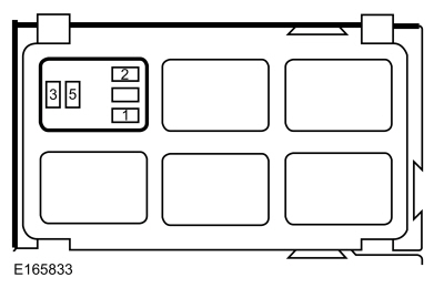
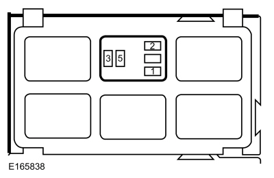
(driver or passenger) heated seat relay (located in the CJB
. When the heated seat relay is activated, voltage is supplied to the
heater mats. The heater mats are directly connected to ground to
complete the electrical circuit to heat the seat.
Possible Sources:
-
Fuse
-
Wiring, terminals or connectors
-
BCM
Visual Inspection and Diagnostic Pre-checks
-
Verify CJB fuse 17 (15A) is OK.
PINPOINT TEST A: THE HEATED SEATS ARE BOTH INOPERATIVE — DRIVER AND PASSENGER
| A1 CHECK FOR VOLTAGE TO THE DRIVER HEATED SEAT RELAY |
-
Disconnect: Driver Heated Seat Relay.
-
Measure:
|
Positive Lead
|
Measurement / Action
|
Negative Lead
|
 Driver heated seat relay, socket pin 1.
|

|
Ground
|
Is the voltage greater than 11 volts?
| No |
VERIFY CJB
fuse 17 (15A) is OK. If OK, REPAIR the circuit. If not OK, REFER to
the Wiring Diagrams manual to identify the possible causes of the
circuit short.
|
|
| A2 CHECK THE HEATED SEAT SWITCH GROUND CIRCUIT |
-
Disconnect: Driver Heated Seat Switch C2400.
-
Measure:
Click to display connectors
|
Positive Lead
|
Measurement / Action
|
Negative Lead
|
|
C2400-4
|
|
Ground
|
Is the resistance less than 3 ohms?
|
| A3 CHECK THE BCM (BODY CONTROL MODULE)
FOR CORRECT OPERATION |
-
Disconnect and inspect all the BCM connectors.
-
Repair:
-
corrosion (install new connector or terminals - clean module pins)
-
damaged or bent pins - install new terminals/pins as necessary
-
pushed-out pins - install new pins as necessary
-
Reconnect the BCM connectors and all previously disconnected rear
window defrost system connectors. Make sure they seat and latch
correctly.
-
Operate the system and determine if the concern is still present.
Is the concern still present?
| Yes |
CHECK OASIS for any applicable Technical Service Bulletins (TSBs). If a
TSB exists for this concern, DISCONTINUE this test and FOLLOW TSB
instructions. If no Technical Service Bulletins (TSBs) address this
concern, INSTALL a new BCM .
REFER to: Body Control Module (BCM) (419-10 Multifunction Electronic Modules, Removal and Installation).
|
| No |
The system is operating correctly at this time. The
concern may have been caused by module connections. ADDRESS the root
cause of any connector or pin issues.
|
|
The heated seat is inoperative/does not operate correctly — driver
Refer to Wiring Diagrams Cell 119 for schematic and connector information.
Normal Operation and Fault Conditions
The
heated seat system only operates when the engine is running. When the
driver or passenger heated seat switch (located on the instrument panel)
is activated, it supplies a ground signal to the BCM . When the BCM
receives the heated seat switch signal, it activates the appropriate
(driver or passenger) heated seat relay (located in the CJB
. When the heated seat relay is activated, voltage is supplied to the
heater mats. The heater mats are directly connected to ground to
complete the electrical circuit to heat the seat.
DTC Fault Trigger Conditions
|
DTC
|
Description
|
Fault Trigger Conditions
|
|
B1034:12
|
Left Front Seat Heater Element: Circuit Short To Battery
|
If the driver heated seat relay control circuit is shorted to voltage
and the BCM attempts to activate the driver heated seat relay, this DTC
sets and the seat fails to heat.
|
|
B1034:14
|
Left Front Seat Heater Element: Circuit Short To Ground or Open
|
If the driver heated seat relay control circuit is open or shorted to
ground and the BCM attempts to activate the driver heated seat relay,
this DTC
sets and the seat fails to heat (circuit open) or may be on at all
times (circuit shorted to ground) until the ignition is turned OFF.
|
|
B115B:23
|
Front Driver Seat Heater: Signal Stuck Low
|
Sets when the BCM detects the driver heated seat switch is active
during on-demand self-test or has been active for more than 2 minutes.
|
Possible Sources
-
Heated seat relay
-
Heated seat switch
-
Wiring, terminals or connectors
-
Heater mat
-
BCM
PINPOINT TEST B: THE HEATED SEAT IS INOPERATIVE/DOES NOT OPERATE CORRECTLY — DRIVER
| B1 RETRIEVE THE BCM (BODY CONTROL MODULE)
DIAGNOSTIC TROUBLE CODES (DTCS) |
-
Using a diagnostic scan tool, perform BCM self-test.
Is DTC B1034:12, B1034:14 or B115B:23 present?
| Yes |
For DTC B1034:14 is present, GO to B7
For DTC B1034:12 is present, GO to B6
For DTC B115B:23 is present, GO to B4
For all other Diagnostic Trouble Codes (DTCs), REFER to the BCM
DTC Chart.
|
| No |
If the cushion and backrest heater mats are both inoperative, GO to B2
If only the cushion heater mat is inoperative, INSTALL a new driver seat cushion heater mat.
If only the backrest heater mat is inoperative, INSTALL a new driver seat backrest heater mat.
|
|
| B2 CHECK THE DRIVER HEATED SEAT (CC_SW_D_HSEATS) PID (PARAMETER IDENTIFICATION)
OPERATION |
-
Using a diagnostic scan tool, view the BCM CC_SW_D_HSEATS PID while pressing and releasing the driver heated seat switch.
Does the PID agree with the driver heated switch status?
|
| B3 CHECK THE DRIVER HEATED SEAT SWITCH GROUND CIRCUIT FOR AN OPEN |
-
Disconnect: Driver Heated Seat Switch C2400.
-
Measure:
Click to display connectors
|
Positive Lead
|
Measurement / Action
|
Negative Lead
|
|
C2400-4
|

|
Ground
|
Is the resistance less than 3 ohms?
|
| B4 CHECK THE BCM (BODY CONTROL MODULE)
DRIVER HEATED SEAT (CC_SW_D_HSEATS) PID (PARAMETER IDENTIFICATION)
OPERATION |
-
Disconnect: Driver Heated Seat Switch C2400.
-
Connect a fused jumper wire between:
Click to display connectors
|
Positive Lead
|
Measurement / Action
|
Negative Lead
|
|
C2400-1
|

|
C2400-4
|
-
Using a diagnostic scan tool, view BCM Parameter Identifications (PIDs).
-
Using a diagnostic scan tool, select the BCM
PID CC_SW_D_HSEATS status.
-
While observing the PID , remove the fused jumper wire.
Did the PID state change when the fused jumper wire was removed?
| Yes |
INSTALL a new driver heated seat switch.
|
|
| B5 CHECK THE DRIVER HEATED SWITCH SIGNAL CIRCUIT FOR AN OPEN OR SHORT TO GROUND |
-
Measure:
Click to display connectors
|
Positive Lead
|
Measurement / Action
|
Negative Lead
|
|
C2400-1
|
|
C2280F-8
|
-
Measure:
Click to display connectors
|
Positive Lead
|
Measurement / Action
|
Negative Lead
|
|
C2400-1
|
|
Ground
|
Is the resistance less than 3 ohms between the heated seat switch and
the BCM ; and greater than 10,000 ohms between the heated seat switch
and ground?
|
| B6 CHECK THE RELAY CONTROL CIRCUIT FOR A SHORT TO VOLTAGE |
-
Disconnect: Driver Heated Seat Relay.
-
Measure:
|
Positive Lead
|
Measurement / Action
|
Negative Lead
|
|
Driver heated seat relay, socket pin 2.
|
|
Ground
|
Is any voltage present?
| No |
INSTALL a new driver heated seat relay. RECONNECT all connectors and
REPEAT the self-test. If the DTC is retrieved again, GO to B13
|
|
| B7 CHECK THE RELAY CONTROL CIRCUIT FOR A SHORT TO GROUND |
-
Disconnect: Driver Heated Seat Relay.
-
Measure:
|
Positive Lead
|
Measurement / Action
|
Negative Lead
|
|
Driver heated seat relay, socket pin 2.
|
|
Ground
|
Is the resistance greater than 10,000 ohms?
|
| B8 CHECK THE RELAY CONTROL CIRCUIT FOR AN OPEN |
-
Measure:
|
Positive Lead
|
Measurement / Action
|
Negative Lead
|
|
Driver heated seat relay, socket pin 2.
|
|
C2280D-5
|
Is the resistance less than 3 ohms?
| Yes |
INSTALL a new driver heated seat relay. RECONNECT all connectors and
REPEAT the self-test. If the DTC is retrieved again, GO to B13
|
|
| B9 CHECK FOR VOLTAGE TO THE DRIVER HEATED SEAT RELAY |
-
Disconnect: Driver Heated Seat Relay.
-
Measure:
|
Positive Lead
|
Measurement / Action
|
Negative Lead
|
|
Driver heated seat relay, socket pin 1.
|
|
Ground
|
|
Driver heated seat relay, socket pin 3.
|
|
Ground
|
Is the voltage greater than 11 volts for both measurements?
|
| B10 CHECK THE HEATER MAT CIRCUIT FOR VOLTAGE |
-
Connect: Driver Heated Seat Relay.
-
Depower the SRS .
REFER to: Supplemental Restraint System (SRS)
Depowering and Repowering (501-20B Supplemental Restraint System,
General Procedures).
-
Disconnect: Driver Seat Side Air Bag Module C367.
-
Disconnect: Driver Seat Cushion Heater C364.
-
 WARNING:
Make sure no one is in the vehicle and there is
nothing blocking or placed in front of any airbag when the battery is
connected. Failure to follow these instructions may result in serious
personal injury in the event of an accidental deployment.
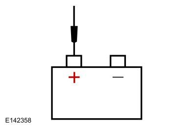
Connect the battery ground cable.
WARNING:
Make sure no one is in the vehicle and there is
nothing blocking or placed in front of any airbag when the battery is
connected. Failure to follow these instructions may result in serious
personal injury in the event of an accidental deployment.
Connect the battery ground cable.
REFER to: Battery Disconnect and Connect (414-01 Battery, Mounting and Cables, General Procedures).
-
Activate the driver heated seat switch.
-
Measure:
Click to display connectors
|
Positive Lead
|
Measurement / Action
|
Negative Lead
|
|
C364-1
|
|
Ground
|
Is the voltage greater than 11 volts?
|
| B11 CHECK THE HEATER CIRCUIT FOR AN OPEN |
-
Driver Heated Seat Relay.
-
Measure:
|
Positive Lead
|
Measurement / Action
|
Negative Lead
|
|
Driver heated seat relay, socket pin 5.
|
|
C364-1
|
Is the resistance less than 3 ohms?
| No |
REPAIR the circuit. CLEAR the Diagnostic Trouble
Codes (DTCs). REPEAT the self-test. TEST the system for normal
operation. DISCONNECT the battery ground cable. CONNECT driver seat
side air bag module C367. REPOWER the SRS .
REFER to: Supplemental
Restraint System (SRS) Depowering and Repowering (501-20B Supplemental
Restraint System, General Procedures).
|
|
| B12 CHECK THE HEATER MAT GROUND CIRCUIT FOR AN OPEN |
-
Measure:
Click to display connectors
|
Positive Lead
|
Measurement / Action
|
Negative Lead
|
|
C364-2
|
|
Ground
|
Is the resistance less than 3 ohms?
| Yes |
CHECK for loose or damaged connector pins and wiring
damage. If OK, INSTALL a new driver seat cushion heater mat. CLEAR the
Diagnostic Trouble Codes (DTCs). REPEAT the self-test. TEST the system
for normal operation. DISCONNECT the battery ground cable. CONNECT
driver seat side air bag module C367. REPOWER the SRS .
REFER to:
Supplemental Restraint System (SRS) Depowering and Repowering (501-20B
Supplemental Restraint System, General Procedures).
|
| No |
REPAIR the circuit. CLEAR the Diagnostic Trouble
Codes (DTCs). REPEAT the self-test. TEST the system for normal
operation. DISCONNECT the battery ground cable. CONNECT driver seat
side air bag module C367. REPOWER the SRS .
REFER to: Supplemental
Restraint System (SRS) Depowering and Repowering (501-20B Supplemental
Restraint System, General Procedures).
|
|
| B13 CHECK THE BCM (BODY CONTROL MODULE)
FOR CORRECT OPERATION |
-
Disconnect all of the BCM connectors.
-
Repair:
-
corrosion (install new connector or terminals - clean module pins)
-
damaged or bent pins - install new terminals/pins as necessary
-
pushed-out pins - install new pins as necessary
-
Reconnect the BCM and all previously disconnected system connectors. Make sure they seat and latch correctly.
-
Operate the system and determine if the concern is still present.
Is the concern still present?
| Yes |
CHECK OASIS for any applicable Technical Service Bulletins (TSBs). If a
TSB exists for this concern, DISCONTINUE this test and FOLLOW TSB
instructions. If no Technical Service Bulletins (TSBs) address this
concern, INSTALL a new BCM .
REFER to: Body Control Module (BCM) (419-10 Multifunction Electronic Modules, Removal and Installation).
|
| No |
The system is operating correctly at this time. The
concern may have been caused by module connections. ADDRESS the root
cause of any connector or pin issues.
|
|
| B14 CHECK THE BCM (BODY CONTROL MODULE)
FOR CORRECT OPERATION |
-
Disconnect all of the BCM connectors.
-
Repair:
-
corrosion (install new connector or terminals - clean module pins)
-
damaged or bent pins - install new terminals/pins as necessary
-
pushed-out pins - install new pins as necessary
-
Reconnect the BCM and all previously disconnected system connectors. Make sure they seat and latch correctly.
-
Operate the system and determine if the concern is still present.
Is the concern still present?
| Yes |
CHECK OASIS for any applicable Technical Service Bulletins (TSBs). If a
TSB exists for this concern, DISCONTINUE this test and FOLLOW TSB
instructions. If no Technical Service Bulletins (TSBs) address this
concern, INSTALL a new BCM .
REFER to: Body Control Module (BCM) (419-10 Multifunction Electronic Modules, Removal and Installation).
DISCONNECT the battery ground cable. CONNECT driver seat side air bag module C367. REPOWER the SRS .
REFER
to: Supplemental Restraint System (SRS) Depowering and Repowering
(501-20B Supplemental Restraint System, General Procedures).
|
| No |
The system is operating correctly at this time. The
concern may have been caused by module connections. ADDRESS the root
cause of any connector or pin issues. DISCONNECT the battery ground
cable. CONNECT driver seat side air bag module C367. REPOWER the SRS .
REFER
to: Supplemental Restraint System (SRS) Depowering and Repowering
(501-20B Supplemental Restraint System, General Procedures).
|
|
The heated seat is inoperative/does not operate correctly — passenger
Refer to Wiring Diagrams Cell 119 for schematic and connector information.
Normal Operation and Fault Conditions
The
heated seat system only operates when the engine is running. When the
driver or passenger heated seat switch (located on the instrument panel)
is activated, it supplies a ground signal to the BCM . When the BCM
receives the heated seat switch signal, it activates the appropriate
(driver or passenger) heated seat relay (located in the CJB
. When the heated seat relay is activated, voltage is supplied to the
heater mats. The heater mats are directly connected to ground to
complete the electrical circuit to heat the seat.
DTC Fault Trigger Conditions
|
DTC
|
Description
|
Fault Trigger Conditions
|
|
B1036:12
|
Right Front Seat Heater Element: Circuit Short To Battery
|
If the passenger heated seat relay control circuit is shorted to
voltage and the BCM attempts to activate the passenger heated seat
relay, this DTC sets and the seat fails to heat.
|
|
B1036:14
|
Right Front Seat Heater Element: Circuit Short To Ground or Open
|
If the passenger heated seat relay control circuit is open or shorted
to ground and the BCM attempts to activate the passenger heated seat
relay, this DTC
sets and the seat fails to heat (circuit open) or may be on at all
times (circuit shorted to ground) until the ignition is turned OFF.
|
|
B115A:23
|
Front Passenger Seat Heater: Signal Stuck Low
|
Sets when the BCM detects the passenger heated seat switch is active
during on-demand self-test or has been active for more than 2 minutes.
|
Possible Sources
-
Heated seat relay
-
Heated seat switch
-
Wiring, terminals or connectors
-
Heater mat
-
BCM
PINPOINT TEST C: THE HEATED SEAT IS INOPERATIVE/DOES NOT OPERATE CORRECTLY — PASSENGER
| C1 RETRIEVE THE BCM (BODY CONTROL MODULE)
DIAGNOSTIC TROUBLE CODES (DTCS) |
-
Using a diagnostic scan tool, perform BCM self-test.
Is DTC B1034:12, B1034:14 or B115B:23 present?
| Yes |
For DTC B1036:14 is present, GO to C7
For DTC B1036:12 is present, GO to C6
For DTC B115A:23 is present, GO to C4
For all other Diagnostic Trouble Codes (DTCs), REFER to the BCM
DTC Chart.
|
| No |
If the cushion and backrest heater mats are both inoperative, GO to C2
If only the cushion heater mat is inoperative, INSTALL a new passenger seat cushion heater mat.
If only the backrest heater mat is inoperative, INSTALL a new passenger seat backrest heater mat.
|
|
| C2 CHECK THE PASSENGER HEATED SEAT (CC_SW_P_HSEATS) PID (PARAMETER IDENTIFICATION)
OPERATION |
-
Using a diagnostic scan tool, view the BCM CC_SW_P_HSEATS PID while pressing and releasing the passenger heated seat switch.
Does the PID agree with the passenger heated switch status?
|
| C3 CHECK THE PASSENGER HEATED SEAT SWITCH GROUND CIRCUIT FOR AN OPEN |
-
Disconnect: Passenger Heated Seat/Ambient Lighting Switch C2401.
-
Measure:
Click to display connectors
|
Positive Lead
|
Measurement / Action
|
Negative Lead
|
|
C2401-4
|
|
Ground
|
Is the resistance less than 3 ohms?
|
| C4 CHECK THE BCM (BODY CONTROL MODULE)
PASSENGER HEATED SEAT (CC_SW_D_HSEATS) PID (PARAMETER IDENTIFICATION)
OPERATION |
-
Disconnect: Passenger Heated Seat/Ambient Lighting Switch C2401.
-
Connect a fused jumper wire between:
Click to display connectors
|
Positive Lead
|
Measurement / Action
|
Negative Lead
|
|
C2401-4
|
|
C2401-6
|
-
Using a diagnostic scan tool, view BCM Parameter Identifications (PIDs).
-
Using a diagnostic scan tool, select the BCM
PID CC_SW_P_HSEATS status.
-
While observing the PID , remove the fused jumper wire.
Did the PID state change when the fused jumper wire was removed?
| Yes |
INSTALL a new passenger heated seat/ambient lighting switch.
|
|
| C5 CHECK THE PASSENGER HEATED SWITCH SIGNAL CIRCUIT FOR AN OPEN OR SHORT TO GROUND |
-
Measure:
Click to display connectors
|
Positive Lead
|
Measurement / Action
|
Negative Lead
|
|
C2401-6
|
|
C2280F-6
|
-
Measure:
Click to display connectors
|
Positive Lead
|
Measurement / Action
|
Negative Lead
|
|
C2401-6
|
|
Ground
|
Is the resistance less than 3 ohms between the heated seat switch and
the BCM ; and greater than 10,000 ohms between the heated seat switch
and ground?
|
| C6 CHECK THE RELAY CONTROL CIRCUIT FOR A SHORT TO VOLTAGE |
-
Disconnect: Passenger Heated Seat Relay.
-
Measure:
|
Positive Lead
|
Measurement / Action
|
Negative Lead
|
 Passenger heated seat relay, socket pin 2.
|
|
Ground
|
Is any voltage present?
| No |
INSTALL a new passenger heated seat relay. RECONNECT all connectors and
REPEAT the self-test. If the DTC DTC is retrieved again, GO to C13
|
|
| C7 CHECK THE RELAY CONTROL CIRCUIT FOR A SHORT TO GROUND |
-
Disconnect: Passenger Heated Seat Relay.
-
Measure:
|
Positive Lead
|
Measurement / Action
|
Negative Lead
|
|
Passenger heated seat relay, socket pin 2.
|
|
Ground
|
Is the resistance greater than 10,000 ohms?
|
| C8 CHECK THE RELAY CONTROL CIRCUIT FOR AN OPEN |
-
Measure:
|
Positive Lead
|
Measurement / Action
|
Negative Lead
|
|
Passenger heated seat relay, socket pin 2.
|
|
C2280D-16
|
Is the resistance less than 3 ohms?
| Yes |
INSTALL a new passenger heated seat relay. RECONNECT all connectors and
REPEAT the self-test. If the DTC is retrieved again, GO to C13
|
|
| C9 CHECK FOR VOLTAGE TO THE PASSENGER HEATED SEAT RELAY |
-
Disconnect: Passenger Heated Seat Relay.
-
Measure:
|
Positive Lead
|
Measurement / Action
|
Negative Lead
|
|
Passenger heated seat relay, socket pin 1.
|
|
Ground
|
|
Passenger heated seat relay, socket pin 3.
|
|
Ground
|
Is the voltage greater than 11 volts for both measurements?
|
| C10 CHECK THE HEATER MAT CIRCUIT FOR VOLTAGE |
-
Connect: Passenger Heated Seat Relay.
-
Depower the SRS .
REFER to: Supplemental Restraint System (SRS)
Depowering and Repowering (501-20B Supplemental Restraint System,
General Procedures).
-
Disconnect: Passenger Seat Side Air Bag Module C337.
-
Disconnect: Passenger Seat Cushion Heater C334.
-
WARNING:
Make sure no one is in the vehicle and there is
nothing blocking or placed in front of any airbag when the battery is
connected. Failure to follow these instructions may result in serious
personal injury in the event of an accidental deployment.
Connect the battery ground cable.
REFER to: Battery Disconnect and Connect (414-01 Battery, Mounting and Cables, General Procedures).
-
Activate the passenger heated seat switch.
-
Measure:
Click to display connectors
|
Positive Lead
|
Measurement / Action
|
Negative Lead
|
|
C334-1
|
|
Ground
|
Is the voltage greater than 11 volts?
|
| C11 CHECK THE HEATER CIRCUIT FOR AN OPEN |
-
Passenger Heated Seat Relay.
-
Measure:
|
Positive Lead
|
Measurement / Action
|
Negative Lead
|
|
Passenger heated seat relay, socket pin 5.
|
|
C334-1
|
Is the resistance less than 3 ohms?
| No |
REPAIR the circuit. CLEAR the Diagnostic Trouble
Codes (DTCs). REPEAT the self-test. TEST the system for normal
operation. DISCONNECT the battery ground cable. CONNECT passenger seat
side air bag module C337. REPOWER the SRS .
REFER to: Supplemental
Restraint System (SRS) Depowering and Repowering (501-20B Supplemental
Restraint System, General Procedures).
|
|
| C12 CHECK THE HEATER MAT GROUND CIRCUIT FOR AN OPEN |
-
Measure:
Click to display connectors
|
Positive Lead
|
Measurement / Action
|
Negative Lead
|
|
C334-2
|
|
Ground
|
Is the resistance less than 3 ohms?
| Yes |
CHECK for loose or damaged connector pins and wiring
damage. If OK, INSTALL a new passenger seat cushion heater mat. CLEAR
the Diagnostic Trouble Codes (DTCs). REPEAT the self-test. TEST the
system for normal operation. DISCONNECT the battery ground cable.
CONNECT passenger seat side air bag module C337. REPOWER the SRS .
REFER
to: Supplemental Restraint System (SRS) Depowering and Repowering
(501-20B Supplemental Restraint System, General Procedures).
|
| No |
REPAIR the circuit. CLEAR the Diagnostic Trouble
Codes (DTCs). REPEAT the self-test. TEST the system for normal
operation. DISCONNECT the battery ground cable. CONNECT passenger seat
side air bag module C337. REPOWER the SRS .
REFER to: Supplemental
Restraint System (SRS) Depowering and Repowering (501-20B Supplemental
Restraint System, General Procedures).
|
|
| C13 CHECK THE BCM (BODY CONTROL MODULE)
FOR CORRECT OPERATION |
-
Disconnect all of the BCM connectors.
-
Repair:
-
corrosion (install new connector or terminals - clean module pins)
-
damaged or bent pins - install new terminals/pins as necessary
-
pushed-out pins - install new pins as necessary
-
Reconnect the BCM and all previously disconnected system connectors. Make sure they seat and latch correctly.
-
Operate the system and determine if the concern is still present.
Is the concern still present?
| Yes |
CHECK OASIS for any applicable Technical Service Bulletins (TSBs). If a
TSB exists for this concern, DISCONTINUE this test and FOLLOW TSB
instructions. If no Technical Service Bulletins (TSBs) address this
concern, INSTALL a new BCM .
REFER to: Body Control Module (BCM) (419-10 Multifunction Electronic Modules, Removal and Installation).
|
| No |
The system is operating correctly at this time. The
concern may have been caused by module connections. ADDRESS the root
cause of any connector or pin issues.
|
|
| C14 CHECK THE BCM (BODY CONTROL MODULE)
FOR CORRECT OPERATION |
-
Disconnect all of the BCM connectors.
-
Repair:
-
corrosion (install new connector or terminals - clean module pins)
-
damaged or bent pins - install new terminals/pins as necessary
-
pushed-out pins - install new pins as necessary
-
Reconnect the BCM and all previously disconnected system connectors. Make sure they seat and latch correctly.
-
Operate the system and determine if the concern is still present.
Is the concern still present?
| Yes |
CHECK OASIS for any applicable Technical Service Bulletins (TSBs). If a
TSB exists for this concern, DISCONTINUE this test and FOLLOW TSB
instructions. If no Technical Service Bulletins (TSBs) address this
concern, INSTALL a new BCM .
REFER to: Body Control Module (BCM) (419-10 Multifunction Electronic Modules, Removal and Installation).
DISCONNECT the battery ground cable. CONNECT passenger seat side air bag module C337. REPOWER the SRS .
REFER
to: Supplemental Restraint System (SRS) Depowering and Repowering
(501-20B Supplemental Restraint System, General Procedures).
|
| No |
The system is operating correctly at this time. The
concern may have been caused by module connections. ADDRESS the root
cause of any connector or pin issues. DISCONNECT the battery ground
cable. CONNECT passenger seat side air bag module C337. REPOWER the SRS .
REFER
to: Supplemental Restraint System (SRS) Depowering and Repowering
(501-20B Supplemental Restraint System, General Procedures).
|
|
The heated seat does not operate correctly — driver or passenger seat heats when the system is off
Refer to Wiring Diagrams Cell 119 for schematic and connector information.
Normal Operation and Fault Conditions
The
heated seat system only operates when the engine is running. When the
driver or passenger heated seat switch (located on the instrument panel)
is activated, it supplies a ground signal to the BCM . When the BCM
receives the heated seat switch signal, it activates the appropriate
(driver or passenger) heated seat relay (located in the CJB
). When the heated seat relay is activated, voltage is supplied to the
cushion heater mat. The cushion heater mats are directly connected to
ground to complete the electrical circuit to heat the seat.
DTC Fault Trigger Conditions
|
DTC
|
Description
|
Fault Trigger Conditions
|
|
B1034:14
|
Left Front Seat Heater Element: Circuit Short To Ground or Open
|
If the driver heated seat relay control circuit is open or shorted to
ground and the BCM attempts to activate the driver heated seat relay,
this DTC
sets and the seat fails to heat (circuit open) or may be on at all
times (circuit shorted to ground) until the ignition is turned OFF.
|
|
B1036:14
|
Right Front Seat Heater Element: Circuit Short To Ground or Open
|
If the passenger heated seat relay relay control circuit is open or
shorted to ground and the BCM attempts to activate the passenger heated
seat relay, this DTC
sets and the seat fails to heat (circuit open) or may be on at all
times (circuit shorted to ground) until the ignition is turned OFF.
|
Possible Sources
-
Heated seat relay
-
Wiring, terminals or connectors
-
BCM
PINPOINT TEST D: THE HEATED SEAT DOES NOT OPERATE CORRECTLY — DRIVER OR PASSENGER SEAT HEATS WHEN THE SYSTEM IS OFF
| D1 CHECK THE RELAY OUTPUT CIRCUIT FOR A SHORT TO VOLTAGE |
-
Disconnect: Driver or Passenger Heated Seat Relay.
-
For driver heated seat, measure:
|
Positive Lead
|
Measurement / Action
|
Negative Lead
|
|
Driver heated seat relay, socket pin 5.
|
|
Ground
|
-
For passenger heated seat, measure:
|
Positive Lead
|
Measurement / Action
|
Negative Lead
|
|
Passenger heated seat relay, socket pin 5.
|
|
Ground
|
Is any voltage present?
|
| D2 CHECK THE RELAY CONTROL CIRCUIT FOR A SHORT TO GROUND |
-
For driver heated seat, measure:
|
Positive Lead
|
Measurement / Action
|
Negative Lead
|
|
Driver heated seat relay, socket pin 2.
|
|
Ground
|
-
For passenger heated seat, measure:
|
Positive Lead
|
Measurement / Action
|
Negative Lead
|
|
Passenger heated seat relay, socket pin 2.
|
|
Ground
|
Is the resistance greater than 10,000 ohms?
| Yes |
INSTALL a new driver heated seat relay or passenger
heated seat relay. RECONNECT all connectors. TEST the system for normal
operation. If the concern is still present, GO to D3
|
|
| D3 CHECK THE BCM (BODY CONTROL MODULE)
FOR CORRECT OPERATION |
-
Disconnect all of the BCM connectors.
-
Repair:
-
corrosion (install new connector or terminals - clean module pins)
-
damaged or bent pins - install new terminals/pins as necessary
-
pushed-out pins - install new pins as necessary
-
Reconnect the BCM and all previously disconnected system connectors. Make sure they seat and latch correctly.
-
Operate the system and determine if the concern is still present.
Is the concern still present?
| Yes |
CHECK OASIS for any applicable Technical Service Bulletins (TSBs). If a
TSB exists for this concern, DISCONTINUE this test and FOLLOW TSB
instructions. If no Technical Service Bulletins (TSBs) address this
concern, INSTALL a new BCM .
REFER to: Body Control Module (BCM) (419-10 Multifunction Electronic Modules, Removal and Installation).
|
| No |
The system is operating correctly at this time. The
concern may have been caused by module connections. ADDRESS the root
cause of any connector or pin issues.
|
|
The
heated seat does not operate correctly — driver seat does heat but the
heated seat indicator does not illuminate when pressed
Refer to Wiring Diagrams Cell 119 for schematic and connector information.
Normal Operation and Fault Conditions
The
heated seat system only operates when the engine is running. When the
driver or passenger heated seat switch (located on the instrument panel)
is activated, it supplies a ground signal to the BCM . When the BCM
receives the heated seat switch signal, it activates the appropriate
(driver or passenger) heated seat relay (located in the CJB ). When the
heated seat relay is activated, the BCM supplies voltage to illuminate
the heated seat switch indicator.
Possible Sources
-
Wiring, terminals or connectors
-
Heated seat switch
-
BCM
PINPOINT TEST E: THE HEATED SEAT DOES NOT OPERATE
CORRECTLY — DRIVER SEAT DOES HEAT BUT THE HEATED SEAT INDICATOR DOES NOT
ILLUMINATE WHEN PRESSED
| E1 CHECK THE INDICATOR CIRCUIT FOR A SHORT TO GROUND |
-
Disconnect: Driver Heated Seat Switch C2400.
-
Measure:
Click to display connectors
|
Positive Lead
|
Measurement / Action
|
Negative Lead
|
|
C2400-2
|
|
Ground
|
Is the resistance greater than 10,000 ohms?
|
| E2 CHECK THE INDICATOR CIRCUIT FOR AN OPEN |
-
Measure:
Click to display connectors
|
Positive Lead
|
Measurement / Action
|
Negative Lead
|
|
C2400-2
|
|
C2280E-15
|
Is the resistance less than 3 ohms?
|
| E3 CHECK THE INDICATOR OPERATION |
-
Connect: Driver Heated Seat Switch C2400.
-
While observing the heated seat switch indicator, momentarily connect a fused jumper wire between:
|
Positive Lead
|
Measurement / Action
|
Negative Lead
|
 Battery positive
|
|
C2280E-15
|
Did the heated seat switch indicator illuminate when the fused jumper wire was connected?
| No |
INSTALL a new driver heated seat switch.
|
|
| E4 CHECK THE BCM (BODY CONTROL MODULE)
FOR CORRECT OPERATION |
-
Disconnect all of the BCM connectors.
-
Repair:
-
corrosion (install new connector or terminals - clean module pins)
-
damaged or bent pins - install new terminals/pins as necessary
-
pushed-out pins - install new pins as necessary
-
Reconnect the BCM and all previously disconnected system connectors. Make sure they seat and latch correctly.
-
Operate the system and determine if the concern is still present.
Is the concern still present?
| Yes |
CHECK OASIS for any applicable Technical Service Bulletins (TSBs). If a
TSB exists for this concern, DISCONTINUE this test and FOLLOW TSB
instructions. If no Technical Service Bulletins (TSBs) address this
concern, INSTALL a new BCM .
REFER to: Body Control Module (BCM) (419-10 Multifunction Electronic Modules, Removal and Installation).
|
| No |
The system is operating correctly at this time. The
concern may have been caused by module connections. ADDRESS the root
cause of any connector or pin issues.
|
|
The
heated seat does not operate correctly — passenger seat does heat but
the heated seat indicator does not illuminate when pressed
Refer to Wiring Diagrams Cell 119 for schematic and connector information.
Normal Operation and Fault Conditions
The
heated seat system only operates when the engine is running. When the
driver or passenger heated seat switch (located on the instrument panel)
is activated, it supplies a ground signal to the BCM . When the BCM
receives the heated seat switch signal, it activates the appropriate
(driver or passenger) heated seat relay (located in the CJB ). When the
heated seat relay is activated, the BCM supplies voltage to illuminate
the heated seat switch indicator.
Possible Sources
-
Wiring, terminals or connectors
-
Heated seat switch
-
BCM
PINPOINT TEST F: THE HEATED SEAT DOES NOT OPERATE
CORRECTLY — PASSENGER SEAT DOES HEAT BUT THE HEATED SEAT INDICATOR DOES
NOT ILLUMINATE WHEN PRESSED
| F1 CHECK THE INDICATOR CIRCUIT FOR A SHORT TO GROUND |
-
Disconnect: Passenger Heated Seat/Ambient Lighting Switch C2401.
-
Measure:
Click to display connectors
|
Positive Lead
|
Measurement / Action
|
Negative Lead
|
|
C2401-3
|
|
Ground
|
Is the resistance greater than 10,000 ohms?
|
| F2 CHECK THE INDICATOR CIRCUIT FOR AN OPEN |
-
Measure:
Click to display connectors
|
Positive Lead
|
Measurement / Action
|
Negative Lead
|
|
C2401-3
|
|
C2280E-3
|
Is the resistance less than 3 ohms?
|
| F3 CHECK THE INDICATOR OPERATION |
-
Connect: Passenger Heated Seat/Ambient Lighting Switch C2401.
-
While observing the heated seat switch indicator, momentarily connect a fused jumper wire between:
|
Positive Lead
|
Measurement / Action
|
Negative Lead
|
|
Battery positive
|
|
C2280E-3
|
Did the heated seat switch indicator illuminate when the fused jumper wire was connected?
| No |
INSTALL a new passenger heated seat/ambient lighting switch.
|
|
| F4 CHECK THE BCM (BODY CONTROL MODULE)
FOR CORRECT OPERATION |
-
Disconnect all of the BCM connectors.
-
Repair:
-
corrosion (install new connector or terminals - clean module pins)
-
damaged or bent pins - install new terminals/pins as necessary
-
pushed-out pins - install new pins as necessary
-
Reconnect the BCM and all previously disconnected system connectors. Make sure they seat and latch correctly.
-
Operate the system and determine if the concern is still present.
Is the concern still present?
| Yes |
CHECK OASIS for any applicable Technical Service Bulletins (TSBs). If a
TSB exists for this concern, DISCONTINUE this test and FOLLOW TSB
instructions. If no Technical Service Bulletins (TSBs) address this
concern, INSTALL a new BCM .
REFER to: Body Control Module (BCM) (419-10 Multifunction Electronic Modules, Removal and Installation).
|
| No |
The system is operating correctly at this time. The
concern may have been caused by module connections. ADDRESS the root
cause of any connector or pin issues.
|
|
The heated seat does not operate correctly — driver or passenger heated seat indicator is always on
Refer to Wiring Diagrams Cell 119 for schematic and connector information.
Normal Operation and Fault Conditions
The
heated seat system only operates when the engine is running. When the
driver or passenger heated seat switch (located on the instrument panel)
is activated, it supplies a ground signal to the BCM . When the BCM
receives the heated seat switch signal, it activates the appropriate
(driver or passenger) heated seat relay (located in the CJB ). When the
heated seat relay is activated, the BCM supplies voltage to illuminate
the heated seat switch indicator.
Possible Sources
-
Wiring, terminals or connectors
-
BCM
PINPOINT TEST G: THE HEATED SEAT DOES NOT OPERATE CORRECTLY — DRIVER OR PASSENGER HEATED SEAT INDICATOR IS ALWAYS ON
| G1 CHECK THE INDICATOR CIRCUIT FOR A SHORT TO VOLTAGE |
-
Observe the affected heated seat switch.
Is the affected heated seat switch indicator illuminated?
| Yes |
REPAIR the heated seat switch indicator circuit for a short to voltage.
|
|
| G2 CHECK THE BCM (BODY CONTROL MODULE)
FOR CORRECT OPERATION |
-
Disconnect all of the BCM connectors.
-
Repair:
-
corrosion (install new connector or terminals - clean module pins)
-
damaged or bent pins - install new terminals/pins as necessary
-
pushed-out pins - install new pins as necessary
-
Reconnect the BCM and all previously disconnected system connectors. Make sure they seat and latch correctly.
-
Operate the system and determine if the concern is still present.
Is the concern still present?
| Yes |
CHECK OASIS for any applicable Technical Service Bulletins (TSBs). If a
TSB exists for this concern, DISCONTINUE this test and FOLLOW TSB
instructions. If no Technical Service Bulletins (TSBs) address this
concern, INSTALL a new BCM .
REFER to: Body Control Module (BCM) (419-10 Multifunction Electronic Modules, Removal and Installation).
|
| No |
The system is operating correctly at this time. The
concern may have been caused by module connections. ADDRESS the root
cause of any connector or pin issues.
|
|
System Operation
Heated Seat Operation
The
heated seat system only operates when the engine is running. When the
driver or passenger heated seat control switch (located on the
instrument panel) is activated, it supplies a momentary ground signal to
the BCM ...
Removal
WARNING:
The following procedure describes critical repair steps
required for correct seat component installation. Follow all notes and
steps carefully...
Other information:
Overview
The fuel system:
is a variable speed Closed Loop Pressure Control (CLPC)
Fuel System with Gasoline Turbocharged Direct Injection (GTDI).
uses a single-container fuel tank.
has a high pressure Fuel Pump that supplies high pressure, low volume fuel pressure to the fuel rails...
Removal
WARNING:
The following procedure prescribes critical repair steps
required for correct restraint system operation during a crash. Follow
all notes and steps carefully. Failure to follow step instructions may
result in incorrect operation of the restraint system and increases the
risk of serious personal injury or death in a crash...
 Seats - System Operation and Component Description. Description and Operation
 Front Seat. Removal and Installation
 Loosen the parking brake cable adjustment nut.