Ford Fiesta: Manual Transmission External Controls - 5-Speed Manual Transmission – B5/IB5/6-Speed Manual Transmission – B6 / External Controls - Overview. Description and Operation
Overview
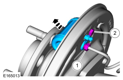
The manual transmission external controls consists of the following:
-
Gearshift Cables
- shift cable
- selector cable
- Gearshift lever
- Gearshift lever knob and boot
- Transmission shift lever
- Transmission selector lever
System Operation
The
manual transmission is controlled by a floor-mounted gearshift lever
located in the floor console. Connection between the floor-mounted
gearshift lever and the manual transmission gearshift control assembly
is made through 2 gearshift cables. When the operator moves the floor
mounted gearshift lever, that movement is transmitted through 2
gearshift cables routed through the body to the transmission. The 2
gearshift cables are attached to the transmission at the gearshift
control assembly. The gearshift control assembly transfers the movement
of the gearshift cables to the shift rods and shift forks located inside
the transmission. Removal and installation of the gearshift cables
requires specific adjustments for correct shifting of the transmission.
Refer to: Gearshift Cable Adjustment - Vehicles With: 5-Speed Manual Transmission - B5/IB5 (308-06A)
.
Refer to: Gearshift Cable Adjustment - 6-Speed Manual Transmission – B6
(308-06 Manual Transmission External Controls - 5-Speed Manual
Transmission – B5/IB5/6-Speed Manual Transmission – B6, General
Procedures).

 External Controls. Description and Operation
Component Location
IB5
Item
Part Number
Description
1
7C4537C453
Gearshift lever
2
7E3957E395
Gearshift cable assembly
3
—
Gearshift cables grommet (part of 7E395)
4
W706131W706131
Gearshift cables grommet nuts
5
7C2817C281
Gearshift cable clip (1...
Other information:
Ford Fiesta 2014 - 2019 Service Manual: Windshield Glass. Removal and Installation
Special Tool(s) / General Equipment 300-AST1770EDeluxe Air Knife Glass Removal Suction Cup Wooden Block Materials Name Specification Sika® SikaTack® MACH 60 / Sika® SikaTack® MACH 30 / Dow® BETASEAL™ Express - Sika Tack ASAP Urethane Adhesive - Dow Urethane One Step Glass PrimerBetaprime™ 5500/5500A/5..
Ford Fiesta 2014 - 2019 Service Manual: Roof Opening Panel Motor. Removal and Installation
Special Tool(s) / General Equipment Wooden Block Interior Trim Remover Removal NOTE: Removal steps in this procedure may contain installation details. Remove the A-pillar trim panel. Refer to: A-Pillar Trim Panel (501-05 Interior Trim and Ornamentation, Removal and Installation). Remove the B-pillar trim panel. Refer to: B-Pil..
Categories
- Manuals Home
- Ford Fiesta Service Manual (2014 - 2019)
- Manual Transmission - 6-Speed Manual Transmission – B6
- Front Strut and Spring Assembly. Removal and Installation
- Camshafts. Removal and Installation
- Valve Cover. Removal and Installation
- Cylinder Head. Removal and Installation
Brake Backing Plate. Removal and Installation
Removal
NOTE: Removal steps in this procedure may contain installation details.
Remove the brake shoes.Refer to: Brake Shoes (206-02 Drum Brake, Removal and Installation).
Disconnect the brake tube fitting.
Torque: 159 lb.in (18 Nm) Remove the bolt and wheel cylinder.
Torque: 106 lb.in (12 Nm)
 Disconnect the brake shoe lever fitting and re