Ford Fiesta: Rear Suspension / Wheel Studs. Removal and Installation
Special Tool(s) / General Equipment
 |
211-001
(TOOL-3290-D)
Remover, Tie-Rod End |
Removal
NOTICE: Suspension fasteners are critical parts that affect performance of vital components and systems. Failure of these fasteners may result in major service expense. Use the same or equivalent parts if replacement is necessary. Do not use a replacement part of lesser quality or substitute design. Tighten fasteners as specified.
-
Remove the brake drum.
Refer to: Brake Drum (206-02 Drum Brake, Removal and Installation).
-
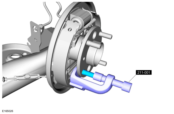
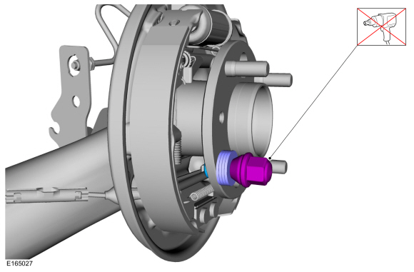
NOTICE: Never use a hammer to remove a wheel stud. Damage to the wheel hub may result.
Press the wheel stud from the wheel bearing and wheel hub flange.
Use Special Service Tool: 211-001 (TOOL-3290-D) Remover, Tie-Rod End.
 |
Installation
-
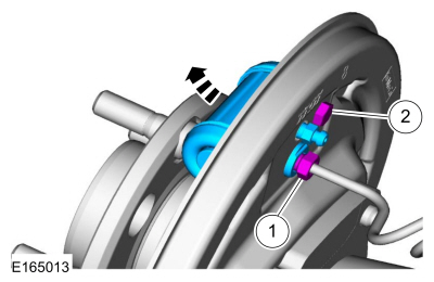
NOTE: Make sure to use washers that have an ID that is larger than the OD of the wheel stud serrations. Use enough washers (approximately 3 to 4) to allow the wheel stud to fully seat against the hub flange.
-
Tighten the wheel nut until the stud is seated against the hub flange.
-
Discard the nut.
-
Tighten the wheel nut until the stud is seated against the hub flange.
 |
-
Install the brake drum.
Refer to: Brake Drum (206-02 Drum Brake, Removal and Installation).
 Wheel Knuckle - 1.6L EcoBoost (132kW/180PS) – Sigma. Removal and Installation
Removal
NOTICE:
Suspension fasteners are critical parts that affect
performance of vital components and systems. Failure of these fasteners
may result in major service expense...
 Wheel Studs - 1.6L EcoBoost (132kW/180PS) – Sigma. Removal and Installation
Special Tool(s) /
General Equipment
211-001
(TOOL-3290-D)
Remover, Tie-Rod End
Removal
NOTICE:
Suspension fasteners are critical parts that affect
performance of vital components and systems...
Other information:
Ford Fiesta 2014 - 2019 Service Manual: Stoplamps. Diagnosis and Testing
Diagnostics in this manual assume a certain skill level and knowledge of Ford-specific diagnostic practices. REFER to: Diagnostic Methods (100-00 General Information, Description and Operation). DTC Chart: BCM BCM DTC Chart BCM Description Action C1A96:24 Brake Light..
Ford Fiesta 2014 - 2019 Service Manual: Audio Unit Antenna Cable. Removal and Installation
Special Tool(s) / General Equipment Interior Trim Remover Removal NOTE: Removal steps in this procedure may contain installation details. NOTE: The AM / FM /Satellite radio antenna cables are part of the vehicle wiring harness. Because the cables cannot be removed from the harness, this procedure applies to the replacement of the cables only. Front cable..
Categories
- Manuals Home
- Ford Fiesta Service Manual (2014 - 2019)
- Manual Transmission - 6-Speed Manual Transmission – B6
- Camshafts. Removal and Installation
- Engine Component View. Description and Operation
- Cylinder Head. Removal and Installation
- Engine
Brake Backing Plate. Removal and Installation
Removal
NOTE: Removal steps in this procedure may contain installation details.
Remove the brake shoes.Refer to: Brake Shoes (206-02 Drum Brake, Removal and Installation).
Disconnect the brake tube fitting.
Torque: 159 lb.in (18 Nm) Remove the bolt and wheel cylinder.
Torque: 106 lb.in (12 Nm)
 Disconnect the brake shoe lever fitting and re