Ford Fiesta: Climate Control System - General Information / Thermostatic Expansion Valve. Removal and Installation
Ford Fiesta 2014 - 2019 Service Manual / Climate Control System / Climate Control System - General Information / Thermostatic Expansion Valve. Removal and Installation
Removal
NOTE: Removal steps in this procedure may contain installation details.
All vehicles
-
Recover the refrigerant.
Refer to: Air Conditioning (A/C) System Recovery, Evacuation and Charging (412-00 Climate Control System - General Information) .
1.6L
-
Remove the air cleaner outlet pipe.
Refer to: Air Cleaner Outlet Pipe (303-12B Intake Air Distribution and Filtering - 1.6L EcoBoost (132kW/180PS) – Sigma, Removal and Installation).
-
-
Disconnect the fuel evaporative tube quick release coupling.
Refer to: Quick Release Coupling (310-00B Fuel System - General Information - 1.6L EcoBoost (132kW/180PS) – Sigma, General Procedures).
-
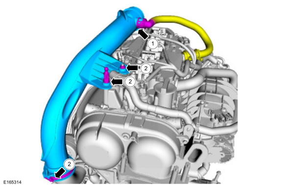
Remove the TC air inlet pipe retaining nut, the engine cover mounting
stud, then loosen the TC air inlet pipe clamp and remove the TC air
inlet pipe.
Torque: 44 lb.in (5 Nm)
-
Disconnect the fuel evaporative tube quick release coupling.
 |
1.0L EcoBoost (90kW/120PS)
-
-
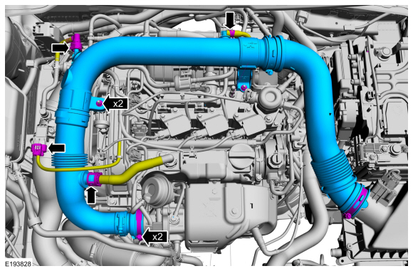
Disconnect the turbocharger boost pressure and
charge air cooler temperature sensor electrical connector.
-
Disconnect the fuel evaporative tube quick release coupling and disconnect the PCV couplings.
-
Remove the air cleaner outlet pipe nuts.
Torque: 97 lb.in (11 Nm)
-
Loosen the air cleaner outlet pipe clamp and remove the air cleaner outlet pipe assembly.
Torque: 35 lb.in (4 Nm)
-
Disconnect the turbocharger boost pressure and
charge air cooler temperature sensor electrical connector.
 |
All vehicles
-
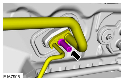
NOTICE: Make sure that all openings are sealed.
Remove the evaporator inlet and outlet manifold studbolt, disconnect the fitting.
Torque: 133 lb.in (15 Nm)
 |
-
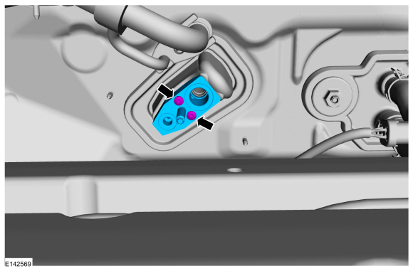
NOTICE: Make sure that all openings are sealed.
Remove the bolts and the thermostatic expansion valve.
Torque: 71 lb.in (8 Nm)
 |
Installation
NOTE: Install new O-rings seals.
-
To install, reverse the removal procedure.
-
Lubricate the refrigerant system with the correct amount of clean PAG oil.
Refer to: Refrigerant Oil Adding (412-00 Climate Control System - General Information) .
 Temperature Door Actuator. Removal and Installation
Removal
NOTE:
Removal steps in this procedure may contain installation details.
Remove the heater core and evaporator core housing - vehicles with: EMTC ...

Other information:
Ford Fiesta 2014 - 2019 Service Manual: SYNC Module [APIM]. Removal and Installation
Removal NOTE: Removal steps in this procedure may contain installation details. Remove the FDIM . Refer to: Front Display Interface Module (FDIM) (415-00B Information and Entertainment System - General Information - Vehicles With: AM/FM/CD/SYNC/Touchscreen Display, Removal and Installation). Remove the screws and separate the APIM from the FDIM ...
Ford Fiesta 2014 - 2019 Service Manual: Evaporator Outlet Line - 1.6L EcoBoost (132kW/180PS) – Sigma. Removal and Installation
Removal NOTE: Removal steps in this procedure may contain installation details. Remove the air cleaner outlet pipe. Refer to: Air Cleaner Outlet Pipe (303-12B Intake Air Distribution and Filtering - 1.6L EcoBoost (132kW/180PS) – Sigma, Removal and Installation). Disconnect the fuel evaporative tube quick release coupling. Refer to: Quick ..
Categories
- Manuals Home
- Ford Fiesta Service Manual (2014 - 2019)
- Front Strut and Spring Assembly. Removal and Installation
- Engine Cooling - 1.6L EcoBoost (132kW/180PS) – Sigma
- Fuel Pump. Removal and Installation
- Camshafts. Removal and Installation
- Engine System - General Information
Rear Wheel Speed Sensor. Removal and Installation
Removal
NOTE: Removal steps in this procedure may contain installation details.
Remove the retainer and pull the rear splash shield outward.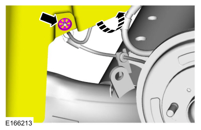 Disconnect the electrical connector and detach the wiring retainer.
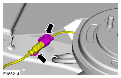
Copyright © 2026 www.fofiesta7.com