Ford Fiesta: Seatbelt Systems / Seatbelt Shoulder Height Adjuster. Removal and Installation
Ford Fiesta 2014 - 2019 Service Manual / Body and Paint / Seatbelt Systems / Seatbelt Shoulder Height Adjuster. Removal and Installation
Removal
NOTE: Removal steps in this procedure may contain installation details.
-
Remove the B-pillar trim panel.
Refer to: B-Pillar Trim Panel (501-05 Interior Trim and Ornamentation, Removal and Installation).
-
-
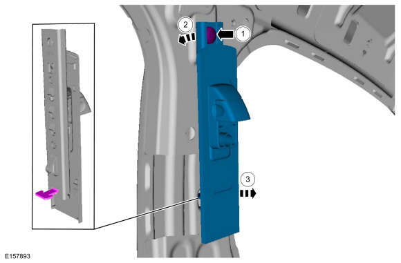
Remove the bolt.
Torque: 30 lb.ft (40 Nm)
-
Rotate the seatbelt shoulder height adjuster to release the locking tab.
-
Remove the seatbelt shoulder height adjuster.
-
Remove the bolt.
 |
Installation
-
NOTE: During installation, make sure the seatbelt webbing is not twisted and the seatbelts and buckles are accessible to the occupants.
To install, reverse the removal procedure.
-
Check the seatbelt system for correct operation.
Refer to: Seatbelt Systems (501-20A Seatbelt Systems, Diagnosis and Testing).
 Seatbelt Retractor and Pretensioner. Removal and Installation
Removal
NOTE:
Removal steps in this procedure may contain installation details.
Depower the SRS .
Refer to: Supplemental Restraint System (SRS) Depowering and Repowering
(501-20B Supplemental Restraint System, General Procedures)...
 Child Safety Seat Tether Anchor. Removal and Installation
Removal
NOTE:
If a child safety seat was in use during a collision,
inspect the child safety seat mounting areas and restore the vehicle to
the original production configuration...
Other information:
Ford Fiesta 2014 - 2019 Service Manual: Rear Door. Removal and Installation
Removal NOTE: LH side shown, RH side similar. NOTE: 5-door shown, 4-door similar. NOTE: Removal steps in this procedure may contain installation details. Remove the check arm bolt. Torque: 18 lb.ft (25 Nm) Disconnect the rear door electrical connector...
Ford Fiesta 2014 - 2019 Service Manual: Halfshaft Bearing - 1.6L EcoBoost (132kW/180PS) – Sigma. Removal and Installation
Special Tool(s) / General Equipment 205-343 (T95P-3514-A) Installer, Constant Velocity Joint Boot ClampTKIT-1995-FTKIT-1995-FM/FLMTKIT-1995-LM/M 205-D064 (D84L-1123-A) Puller, Bearing Flat Headed Screw Driver Hydraulic Press Materials Name Specification Motorcraft® Constant Velocity Joint GreaseXG-5 WSS-M1C258-A1 ..
Categories
- Manuals Home
- Ford Fiesta Service Manual (2014 - 2019)
- Engine
- Engine Component View. Description and Operation
- Engine Cooling - 1.6L EcoBoost (132kW/180PS) – Sigma
- Cylinder Head. Removal and Installation
- Lower Arm. Removal and Installation
Brake Backing Plate. Removal and Installation
Removal
NOTE: Removal steps in this procedure may contain installation details.
Remove the brake shoes.Refer to: Brake Shoes (206-02 Drum Brake, Removal and Installation).
Disconnect the brake tube fitting.
Torque: 159 lb.in (18 Nm) Remove the bolt and wheel cylinder.
Torque: 106 lb.in (12 Nm)
 Disconnect the brake shoe lever fitting and re
Copyright © 2026 www.fofiesta7.com