Ford Fiesta: Supplemental Restraint System / Seat Position Sensor. Removal and Installation
Ford Fiesta 2014 - 2019 Service Manual / Body and Paint / Supplemental Restraint System / Seat Position Sensor. Removal and Installation
Removal
NOTE: Removal steps in this procedure may contain installation details.
-
Turn the ignition OFF and wait at least one minute. WARNING:
Turn the ignition OFF and wait one minute to deplete
the backup power supply. Ignition must remain OFF until repair is
complete. Failure to follow this instruction may result in serious
personal injury or death in the event of an accidental deployment.
WARNING:
Turn the ignition OFF and wait one minute to deplete
the backup power supply. Ignition must remain OFF until repair is
complete. Failure to follow this instruction may result in serious
personal injury or death in the event of an accidental deployment.
-
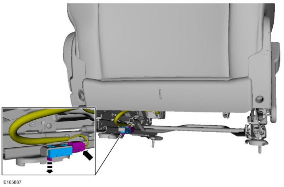
NOTE: LH seat shown, RH seat similar.
-
Remove the retainer.
-
Disconnect the electrical connector.
-
Remove the seat position sensor.
-
Remove the retainer.
 |
Installation
-
To install, reverse the removal procedure.
-
Prove out the SRS
by turning the ignition from ON to OFF. Wait 10 seconds, then turn the
ignition back to ON and monitor the air bag warning indicator with the
air bags installed. The air bag warning indicator illuminates
continuously for approximately 6 seconds and then turns off. If a SRS
fault is present, the air bag warning indicator will fail to light,
remain lit continuously, or flash.
-
The flashing might not occur until approximately 30
seconds after the ignition has been turned from OFF to ON. This is the
time required for the RCM to complete the testing of the SRS . If the air bag warning indicator is inoperative and a SRS
fault exists, a chime sounds in a pattern of 5 sets of 5 beeps. If
this occurs, diagnose and repair the air bag warning indicator and any SRS faults.
-
Clear all continuous Diagnostic Trouble Codes (DTCs) from the RCM and OCSM using a diagnostic scan tool.
 Restraints Control Module (RCM). Removal and Installation
Removal
WARNING:
The following procedure prescribes critical repair steps
required for correct restraint system operation during a crash...
 Side Curtain Airbag. Removal and Installation
Removal
WARNING:
The following procedure prescribes critical repair steps
required for correct restraint system operation during a crash...
Other information:
Ford Fiesta 2014 - 2019 Service Manual: Pinpoint Test - DTC: B. Diagnosis and Testing
B0002:11, B0002:12, B0002:13 and B0002:1A Refer to Wiring Diagrams Cell 46 for schematic and connector information. Normal Operation and Fault Conditions The RCM continuously monitors the driver airbag stage 2 circuits for the following faults: Resistance out of range Unexpected voltage Short to ground Faulted driver airbag If a f..
Ford Fiesta 2014 - 2019 Service Manual: Electronic Engine Controls - Component Location. Description and Operation
Electronic Engine Controls - LH Side of Engine Item Description 1 MAP sensor 2 VCT oil control solenoid 3 CMP sensor - LH 4 Crankcase Pressure sensor 5 PCM 6 MAF sensor 7 Turbocharger boost pressure and charge air temperature sensor 8 Rear KS 9 Front..
Categories
- Manuals Home
- Ford Fiesta Service Manual (2014 - 2019)
- Engine - 1.6L EcoBoost (132kW/180PS) – Sigma
- Engine Component View. Description and Operation
- Engine. Assembly
- Lower Arm. Removal and Installation
- Service Information
Brake Master Cylinder. Removal and Installation
Removal
NOTICE: If the fluid is spilled on the paintwork, the affected area must be immediately washed down with cold water.
NOTE: Removal steps in this procedure may contain installation details.
All vehicles
Remove the battery tray.Refer to: Battery Tray - 1.6L Duratec-16V Ti-VCT (88kW/120PS) – Sigma (414-01 Battery, Mounting and Cables, Removal and Installation).
Refer to: Battery Tray - 1.6L EcoBoost (132kW/180PS) – Sigma (414-01 Battery, Mounting and Cables, Removal and Installation).
Disconnect the vacuum tube from the brake booster and detach the routing clip.
Copyright © 2026 www.fofiesta7.com