Ford Fiesta: Side Panel Sheet Metal Repairs / Rocker Panel - 4-Door. Removal and Installation
Ford Fiesta 2014 - 2019 Service Manual / Body and Paint / Side Panel Sheet Metal Repairs / Rocker Panel - 4-Door. Removal and Installation
Special Tool(s) / General Equipment
| Resistance Spotwelding Equipment | |
| Hot Air Gun | |
| Air Body Saw | |
| MIG/MAG Welding Equipment | |
| Spot Weld Drill Bit | |
| Locking Pliers | |
| Folding Rule |
Materials
| Name | Specification |
|---|---|
| Metal Bonding Adhesive TA-1, TA-1-B, 3M™ 08115, LORD Fusor® 108B, Henkel Teroson EP 5055 |
- |
Removal
-
Refer to: Body Repair Health and Safety and General Precautions (100-00 General Information, Description and Operation). WARNING:
Before beginning any service procedure in this
manual, refer to health and safety warnings in section 100-00 General
Information. Failure to follow this instruction may result in serious
personal injury.
WARNING:
Before beginning any service procedure in this
manual, refer to health and safety warnings in section 100-00 General
Information. Failure to follow this instruction may result in serious
personal injury.
-
Depower the SRS .
Refer to: Supplemental Restraint System (SRS) Depowering and Repowering (501-20B Supplemental Restraint System, General Procedures).
-
Remove the following items:
Refer to: Fender (501-02 Front End Body Panels, Removal and Installation).
Refer to: Rocker Panel Moulding (501-08 Exterior Trim and Ornamentation, Removal and Installation).
Refer to: Front Door (501-03 Body Closures, Removal and Installation).
Refer to: Rear Door (501-03 Body Closures, Removal and Installation).
Refer to: A-Pillar Trim Panel (501-05 Interior Trim and Ornamentation, Removal and Installation).
Refer to: B-Pillar Trim Panel (501-05 Interior Trim and Ornamentation, Removal and Installation).
Refer to: C-Pillar Lower Trim Panel (501-05 Interior Trim and Ornamentation, Removal and Installation).
Refer to: Front Seat (501-10 Seating, Removal and Installation).
Refer to: Rear Seat Cushion (501-10 Seating, Removal and Installation).
Refer to: Rear Seat Backrest (501-10 Seating, Removal and Installation).
-
Remove the hood.
-
Remove the lower door hinges.
-
Remove the rear wheel arch trim.
-
Position the carpeting and wiring harness away from the working area.
-
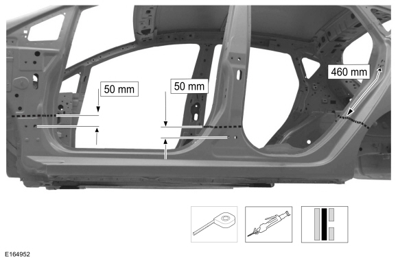
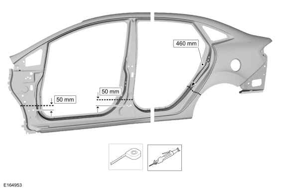
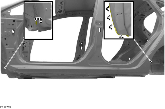
Carefully measure and cut the outer panel only of the body side panel.
Use the General Equipment: Folding Rule
Use the General Equipment: Air Body Saw
 |
-
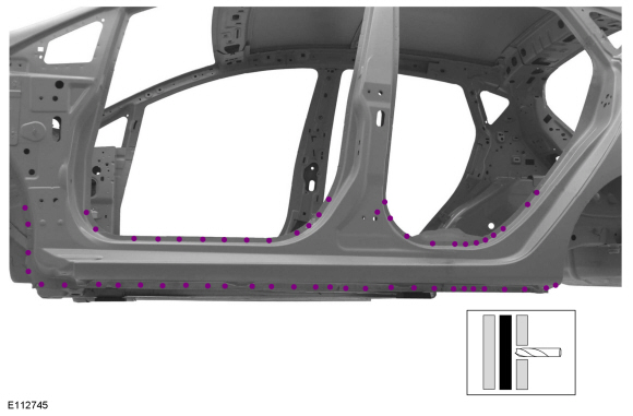
Drill out the spot welds from rocker panel.
Use the General Equipment: Spot Weld Drill Bit
 |
-
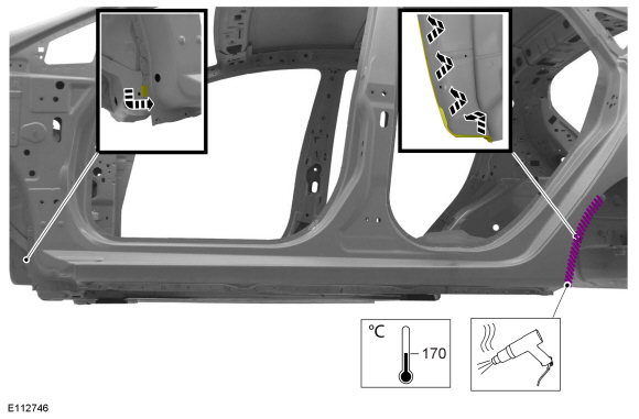
Break the adhesive bond and position aside the wheel arch.
Use the General Equipment: Hot Air Gun
 |
-
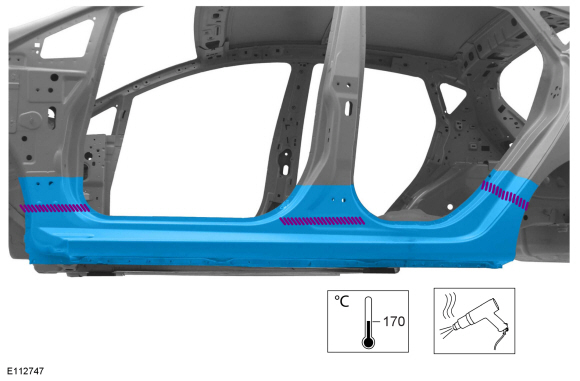
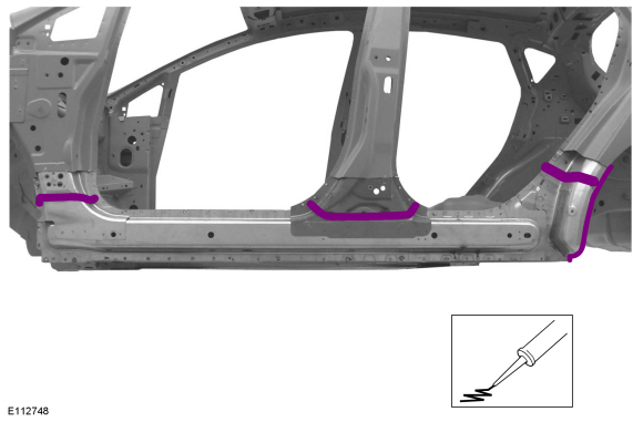
Break the adhesive bond and remove the outer rocker panel section.
Use the General Equipment: Hot Air Gun
 |
Installation
-
Carefully measure and cut the replacement panels to fit repair area.
Use the General Equipment: Folding Rule
Use the General Equipment: Air Body Saw
 |
-
Apply adhesive as indicated.
Material: Metal Bonding Adhesive / TA-1, TA-1-B, 3M™ 08115, LORD Fusor® 108B, Henkel Teroson EP 5055
 |
-
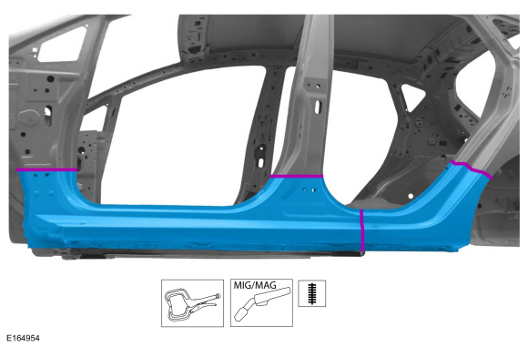
Install, clamp and seam weld the replacement rocker panel sections.
Use the General Equipment: Locking Pliers
Use the General Equipment: MIG/MAG Welding Equipment
 |
-
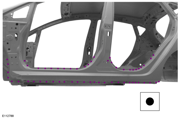
Spot weld the replacement rocker panel.
Use the General Equipment: Resistance Spotwelding Equipment
 |
-
Reposition the wheel arch.
 |
-
Metal finish the repair area using typical metal finishing techniques.
-
Sealing work: All areas must be sealed to production level.
-
Refinish using an approved Ford paint system.
-
Restore corrosion protection.
Refer to: Corrosion Prevention (501-25 Body Repairs - General Information, General Procedures).
-
Reposition the wiring harness and carpet to the original position.
-
Install the rear wheel arch trim.
-
Install the lower door hinges.
-
Install the hood.
-
Install the following items:
Refer to: C-Pillar Lower Trim Panel (501-05 Interior Trim and Ornamentation, Removal and Installation).
Refer to: B-Pillar Trim Panel (501-05 Interior Trim and Ornamentation, Removal and Installation).
Refer to: A-Pillar Trim Panel (501-05 Interior Trim and Ornamentation, Removal and Installation).
Refer to: Rear Seat Backrest (501-10 Seating, Removal and Installation).
Refer to: Rear Seat Cushion (501-10 Seating, Removal and Installation).
Refer to: Front Seat (501-10 Seating, Removal and Installation).
Refer to: Rocker Panel Moulding (501-08 Exterior Trim and Ornamentation, Removal and Installation).
Refer to: Fender (501-02 Front End Body Panels, Removal and Installation).
Refer to: Rear Door (501-03 Body Closures, Removal and Installation).
Refer to: Front Door (501-03 Body Closures, Removal and Installation).
-
Align the following items:
Refer to: Front Door Alignment (501-03 Body Closures, General Procedures).
Refer to: Rear Door Alignment (501-03 Body Closures, General Procedures).
Refer to: Hood Alignment (501-03 Body Closures, General Procedures).
-
Repower the SRS .
Refer to: Supplemental Restraint System (SRS) Depowering and Repowering (501-20B Supplemental Restraint System, General Procedures).

 Rocker Panel - 5-Door. Removal and Installation
Special Tool(s) /
General Equipment
Resistance Spotwelding Equipment
Hot Air Gun
Air Body Saw
MIG/MAG Welding Equipment
Spot Weld Drill Bit
Locking Pliers
Folding Rule
Materials
Name
Specification
Metal Bonding AdhesiveTA-1, TA-1-B, 3M™ 08115, LORD Fusor® 108B, Henkel Teroson EP 5055
-
Removal
..
Other information:
Ford Fiesta 2014 - 2019 Service Manual: Pinpoint Test - DTC: W. Diagnosis and Testing
B1417:11 and B1417:93 Refer to Wiring Diagrams Cell 46 for schematic and connector information. The RCM monitors the RH front impact severity sensor circuits for the following faults: Open circuit Short to voltage Short to ground Faulted RH front impact severity sensor If a fault is detected, the RCM stores DTC B1417:11 or B1417:93 in m..
Ford Fiesta 2014 - 2019 Service Manual: Hood Latch Release Handle. Removal and Installation
Removal Depress the hood latch release handle retaining tab and pull the hood latch release handle. Disconnect the hood release cable from the hood latch release handle. Installation To install, reverse the removal procedure. ..
Categories
- Manuals Home
- Ford Fiesta Service Manual (2014 - 2019)
- Camshafts. Removal and Installation
- Engine
- Engine. Assembly
- Engine Cooling - 1.6L EcoBoost (132kW/180PS) – Sigma
- Lower Arm. Removal and Installation
Component Bleeding. General Procedures
Special Tool(s) / General Equipment
Master Cylinder Bleeding SetBleeding
NOTICE: If the fluid is spilled on the paintwork, the affected area must be immediately washed down with cold water.
Master Cylinder
NOTE: When a new brake master cylinder has been installed, it should be primed to prevent air from entering the system.
NOTE: Make sure the area around the master cylinder cap is clean and free of foreign material.
Remove the brake fluid reservoir cap.Copyright © 2026 www.fofiesta7.com