Ford Fiesta: Side Panel Sheet Metal Repairs / A-Pillar Assembly. Removal and Installation
Ford Fiesta 2014 - 2019 Service Manual / Body and Paint / Side Panel Sheet Metal Repairs / A-Pillar Assembly. Removal and Installation
Special Tool(s) / General Equipment
| Resistance Spotwelding Equipment | |
| Hot Air Gun | |
| 8 mm Drill Bit | |
| MIG/MAG Welding Equipment | |
| Spot Weld Drill Bit |
Materials
| Name | Specification |
|---|---|
| Metal Bonding Adhesive TA-1, TA-1-B, 3M™ 08115, LORD Fusor® 108B, Henkel Teroson EP 5055 |
- |
Removal
-
Refer to: Body Repair Health and Safety and General Precautions (100-00 General Information, Description and Operation). WARNING:
Before beginning any service procedure in this
manual, refer to health and safety warnings in section 100-00 General
Information. Failure to follow this instruction may result in serious
personal injury.
WARNING:
Before beginning any service procedure in this
manual, refer to health and safety warnings in section 100-00 General
Information. Failure to follow this instruction may result in serious
personal injury.
-
Remove the A-piller outer panel.
Refer to: A-Pillar Outer Panel (501-29 Side Panel Sheet Metal Repairs, Removal and Installation).
-
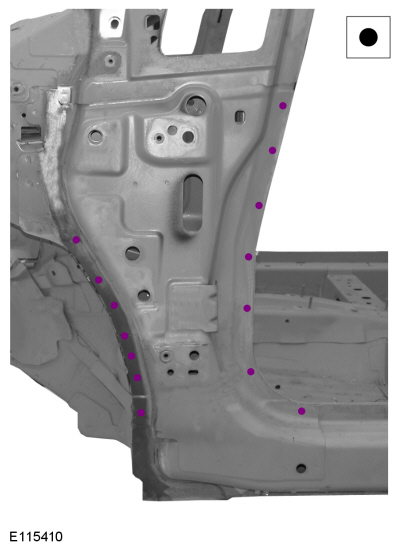
Drill out the spot welds.
Use the General Equipment: Spot Weld Drill Bit
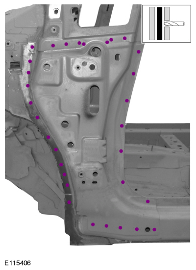 |
-
Break the adhesive bond and remove the A-pillar reinforcement.
Use the General Equipment: Hot Air Gun
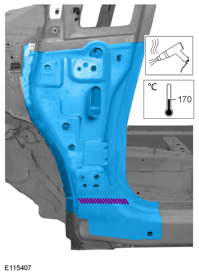 |
Installation
-
Drill plug weld holes in the replacement A-pillar reinforcement.
Use the General Equipment: 8 mm Drill Bit
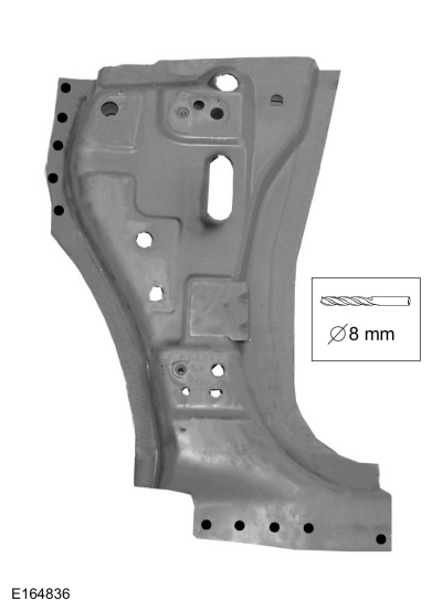 |
-
Apply adhesive and install the replacement A-pillar reinforcement as indicated.
Material: Metal Bonding Adhesive / TA-1, TA-1-B, 3M™ 08115, LORD Fusor® 108B, Henkel Teroson EP 5055
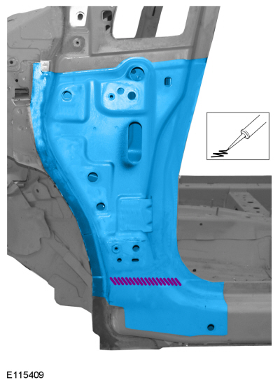 |
-
Spot weld the A-pillar reinforcement.
Use the General Equipment: Resistance Spotwelding Equipment
 |
-
Plug weld the A-pillar reinforcement.
Use the General Equipment: MIG/MAG Welding Equipment
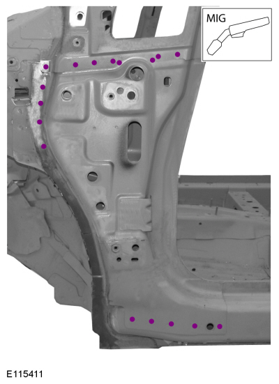 |
-
Install the A-piller outer panel.
Refer to: A-Pillar Outer Panel (501-29 Side Panel Sheet Metal Repairs, Removal and Installation).

 Rocker Panel - 4-Door. Removal and Installation
Special Tool(s) /
General Equipment
Resistance Spotwelding Equipment
Hot Air Gun
Air Body Saw
MIG/MAG Welding Equipment
Spot Weld Drill Bit
Locking Pliers
Folding Rule
Materials
Name
Specification
Metal Bonding AdhesiveTA-1, TA-1-B, 3M™ 08115, LORD Fusor® 108B, Henkel Teroson EP 5055
-
Removal
..
Other information:
Ford Fiesta 2014 - 2019 Service Manual: Steering Column Multifunction Switch LH. Removal and Installation
Removal NOTE: Removal steps in this procedure may contain installation details. Remove the upper steering column shroud. Remove the screws and the lower steering column shroud. Disconnect the electrical connector. Release the tab. Remove..
Ford Fiesta 2014 - 2019 Service Manual: Ignition Lock Cylinder. Removal and Installation
Removal Non-functional lock cylinder NOTE: For non-functional ignition lock cylinders, replace the ingition lock cylinder housing. Replace the ingition lock cylinder housing. Refer to: Ignition Lock Cylinder Housing (211-05 Steering Wheel and Column Electrical Components, Removal and Installation). Functional lock cylinder Remove the Passive Ant..
Categories
- Manuals Home
- Ford Fiesta Service Manual (2014 - 2019)
- Engine
- Manual Transmission - 6-Speed Manual Transmission – B6
- Camshafts. Removal and Installation
- Front Suspension
- Valve Cover. Removal and Installation
Brake Master Cylinder. Removal and Installation
Removal
NOTICE: If the fluid is spilled on the paintwork, the affected area must be immediately washed down with cold water.
NOTE: Removal steps in this procedure may contain installation details.
All vehicles
Remove the battery tray.Refer to: Battery Tray - 1.6L Duratec-16V Ti-VCT (88kW/120PS) – Sigma (414-01 Battery, Mounting and Cables, Removal and Installation).
Refer to: Battery Tray - 1.6L EcoBoost (132kW/180PS) – Sigma (414-01 Battery, Mounting and Cables, Removal and Installation).
Disconnect the vacuum tube from the brake booster and detach the routing clip.
Copyright © 2026 www.fofiesta7.com