Ford Fiesta: Body Closures / Rear Door Alignment. General Procedures
Ford Fiesta 2014 - 2019 Service Manual / Body and Paint / Body Closures / Rear Door Alignment. General Procedures
Inspection
-
Check the body to the rear door dimensions.
Refer to: Body and Frame (501-26 Body Repairs - Vehicle Specific Information and Tolerance Checks, Description and Operation).
Adjustment
NOTE: LH side shown, RH side similar.
NOTE: 5-door shown, 4-door similar.
NOTE: Removal steps in this procedure may contain installation details.
All alignments
-
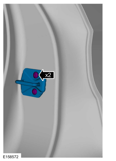
Remove the bolts and the striker assembly.
 |
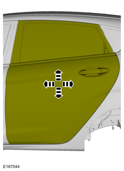
Rear door in and out, up and down alignment
-
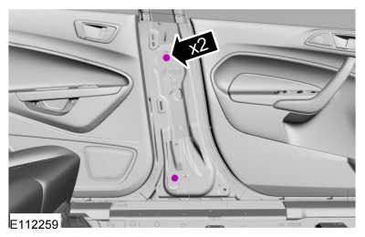
Loosen the bolts to permit movement of the door.
Loosen: 2 turn(s)
 |
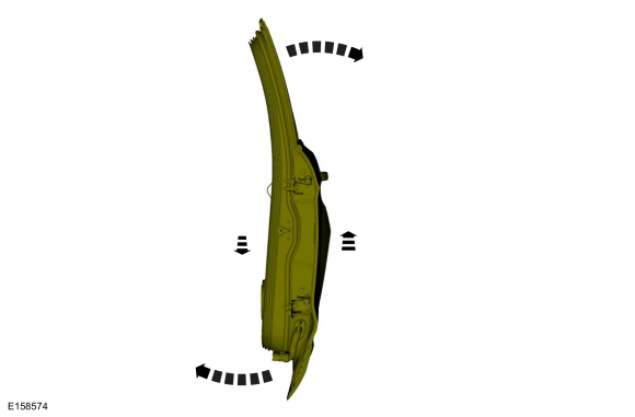
-
Adjust the door to specification.
Refer to: Body and Frame (501-26 Body Repairs - Vehicle Specific Information and Tolerance Checks, Description and Operation).
 |
-
Tighten the bolts.
Torque: 18 lb.ft (24 Nm)
|
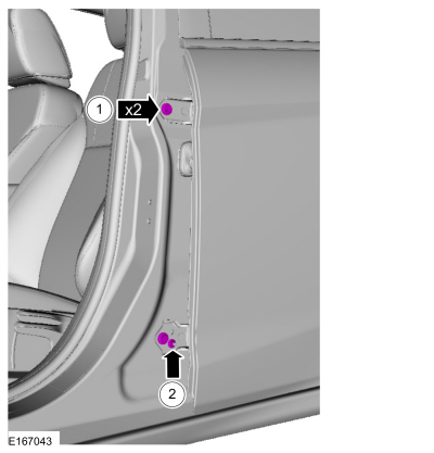
Rear door fore, aft and tilt alignment
-
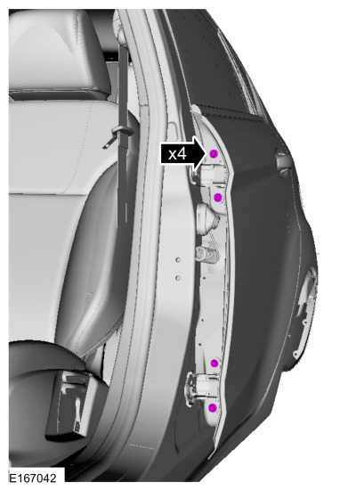
Remove the safety belt retractor and pretensioner.
Refer to: Seatbelt Retractor and Pretensioner (501-20A Seatbelt Systems, Removal and Installation).
-
Loosen the nuts to permit movement of the door.
Loosen: 2 turn(s)
 |
-
Loosen the bolts and nut to permit movement of the door.
Loosen: 2 turn(s)
 |
-
Adjust the door to specification.
Refer to: Body and Frame (501-26 Body Repairs - Vehicle Specific Information and Tolerance Checks, Description and Operation).
 |
-
Tighten the bolts and the nut.
Torque:
1: 18 lb.ft (25 Nm)
2: 106 lb.in (12 Nm)
|
-
Tighten the nuts.
Torque: 18 lb.ft (25 Nm)
|
-
Install the safety belt retractor and pretensioner.
Refer to: Seatbelt Retractor and Pretensioner (501-20A Seatbelt Systems, Removal and Installation).
All alignments
-
Loosen the bolts to permit movement of the striker assembly.
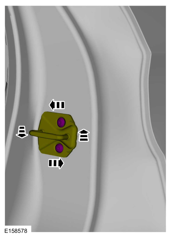 |
-
Tighten the bolts.
Torque: 18 lb.ft (25 Nm)
|
-
Check the body to the rear door dimensions.
Refer to: Body and Frame (501-26 Body Repairs - Vehicle Specific Information and Tolerance Checks, Description and Operation).
 Front Door Alignment. General Procedures
Inspection
Check the body to the front door dimensions.
Refer to: Body and Frame (501-26 Body Repairs - Vehicle Specific Information and Tolerance Checks, Description and Operation)...
 Liftgate Alignment. General Procedures
Inspection
Check the liftgate to the body dimensions.
Refer to: Body and Frame (501-26 Body Repairs - Vehicle Specific Information and Tolerance Checks, Description and Operation)...
Other information:
Ford Fiesta 2014 - 2019 Service Manual: Piston Inspection. General Procedures
Inspection NOTE: Do not use a caustic cleaning solution or a wire brush to clean the pistons or damage can occur. Clean and inspect the (1) ring lands, (2) pin bosses, (3) skirts and the (4) tops of the pistons. If wear marks, scores or glazing is found on the piston skirt, check for a bent or twisted connecting rod...
Ford Fiesta 2014 - 2019 Service Manual: Front Fog Lamp. Removal and Installation
Removal With the vehicle in NEUTRAL, position it on a hoist. Refer to: Jacking and Lifting - Overview (100-02 Jacking and Lifting, Description and Operation). Remove the appropriate wheel and tire. Refer to: Wheel and Tire (204-04A Wheels and Tires, Removal and Installation)...
Categories
- Manuals Home
- Ford Fiesta Service Manual (2014 - 2019)
- Service Information
- Engine System - General Information
- Engine. Assembly
- Engine Cooling - 1.6L EcoBoost (132kW/180PS) – Sigma
- Engine - 1.6L EcoBoost (132kW/180PS) – Sigma
Component Bleeding. General Procedures
Special Tool(s) / General Equipment
Master Cylinder Bleeding SetBleeding
NOTICE: If the fluid is spilled on the paintwork, the affected area must be immediately washed down with cold water.
Master Cylinder
NOTE: When a new brake master cylinder has been installed, it should be primed to prevent air from entering the system.
NOTE: Make sure the area around the master cylinder cap is clean and free of foreign material.
Remove the brake fluid reservoir cap.Copyright © 2026 www.fofiesta7.com