Ford Fiesta: Engine - 1.6L EcoBoost (132kW/180PS) – Sigma / Piston. Disassembly and Assembly of Subassemblies
Ford Fiesta 2014 - 2019 Service Manual / Engine / Engine - 1.6L EcoBoost (132kW/180PS) – Sigma / Piston. Disassembly and Assembly of Subassemblies
Materials
| Name | Specification |
|---|---|
| Engine Oil - SAE 5W-20 - Synthetic Blend Motor Oil XO-5W20-Q1SP |
WSS-M2C945-B1 |
DISASSEMBLY
-
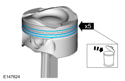
Remove and discard the piston rings.
 |
-
-
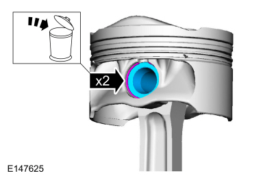
Remove and discard the piston pin retainers.
-
Remove the piston pin.
-
Remove and discard the piston pin retainers.
 |
-
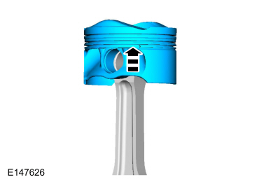
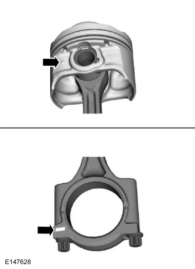
Remove the piston from the connecting rod.
 |
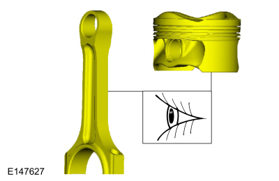
-
Inspect the piston.
Refer to: Piston Inspection (303-00 Engine System - General Information, General Procedures).
 |
ASSEMBLY
-
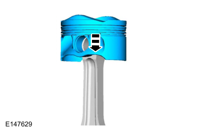
Indicates front of engine.
 |
-
Install the piston to the connecting rod.
 |
-
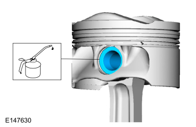
Lubricate with clean engine oil and install the piston pin.
Material: Engine Oil - SAE 5W-20 - Synthetic Blend Motor Oil / XO-5W20-Q1SP (WSS-M2C945-B1)
 |
-
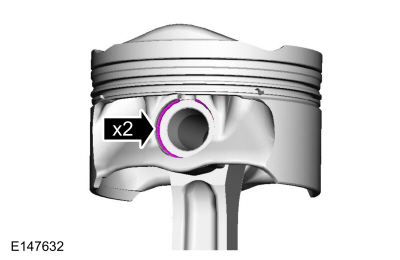
Install the new piston pin retainers.
 |
-
Lubricate with clean engine oil and install the new piston rings.
Material: Engine Oil - SAE 5W-20 - Synthetic Blend Motor Oil / XO-5W20-Q1SP (WSS-M2C945-B1)
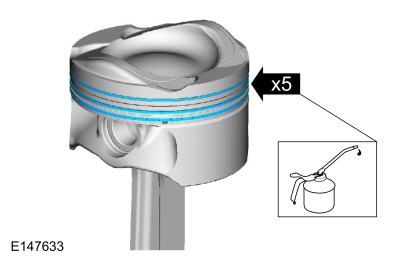 |
-
NOTE: The upper and lower compression rings are to be fitted with the identification marks on the upper side.
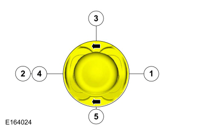
NOTE: Arrows faces the front of the engine.
NOTE: Align the piston rings on the piston.
-
Upper compression ring gap location.
-
Lower compression ring gap location.
-
Upper oil control segment ring gap location.
-
Expander ring gap location.
-
Lower oil control segment ring gap location.
-
Upper compression ring gap location.
 |

 Engine. Assembly
Special Tool(s) /
General Equipment
100-002
(TOOL-4201-C)
Holding Fixture with Dial Indicator Gauge
300-OTC1819E2,200# Floor Crane, Fold Away
303-103
(T74P-6375-A)
Holding Tool, FlywheelT74P-77000-ATKIT-2009TC-F
303-1097Locking Tool, Variable Camshaft Timing Oil Control UnitTKIT-2010B-FLMTKIT-2010B-ROW
303-1502Lifting Device EngineTKI..
Other information:
Ford Fiesta 2014 - 2019 Service Manual: Catalyst Monitor Sensor. Removal and Installation
Materials Name Specification Motorcraft® High Temperature Nickel Anti-Seize LubricantXL-2 - Motorcraft® Penetrating and Lock LubricantXL-1 - Removal With the vehicle in NEUTRAL, position it on a hoist. Refer to: Jacking and Lifting - Overview (100-02 Jacking and Lifting, Description and Operation). Remove..
Ford Fiesta 2014 - 2019 Service Manual: Stoplamp Switch. Removal and Installation
Removal NOTE: Removal steps in this procedure may contain installation details. NOTICE: Do not press, pull or otherwise move the brake pedal while installing the stoplamp switch and cruise control deactivation switch. Install these switches with the booster push rod attached to the brake pedal and with the brake pedal in the at-rest position. Installing these switc..
Categories
- Manuals Home
- Ford Fiesta Service Manual (2014 - 2019)
- Engine - 1.6L EcoBoost (132kW/180PS) – Sigma
- Clutch - 6-Speed Manual Transmission – B6
- Manual Transmission - 6-Speed Manual Transmission – B6
- Engine. Assembly
- Front Strut and Spring Assembly. Removal and Installation
Brake Master Cylinder. Removal and Installation
Removal
NOTICE: If the fluid is spilled on the paintwork, the affected area must be immediately washed down with cold water.
NOTE: Removal steps in this procedure may contain installation details.
All vehicles
Remove the battery tray.Refer to: Battery Tray - 1.6L Duratec-16V Ti-VCT (88kW/120PS) – Sigma (414-01 Battery, Mounting and Cables, Removal and Installation).
Refer to: Battery Tray - 1.6L EcoBoost (132kW/180PS) – Sigma (414-01 Battery, Mounting and Cables, Removal and Installation).
Disconnect the vacuum tube from the brake booster and detach the routing clip.
Copyright © 2026 www.fofiesta7.com