Ford Fiesta: Drum Brake / Brake Shoes. Removal and Installation
Ford Fiesta 2014 - 2019 Service Manual / Brake System / Drum Brake / Brake Shoes. Removal and Installation
Special Tool(s) / General Equipment
| Flat Headed Screw Driver |
Materials
| Name | Specification |
|---|---|
| Motorcraft® Silicone Brake Caliper Grease and Dielectric Compound XG-3-A |
ESA-M1C200-A ESE-M1C171-A |
Removal
NOTE: Removal steps in this procedure may contain installation details.
-
Refer to: Health and Safety Precautions (100-00 General Information, Description and Operation). WARNING:
Before beginning any service procedure in this
manual, refer to health and safety warnings in section 100-00 General
Information. Failure to follow this instruction may result in serious
personal injury.
WARNING:
Before beginning any service procedure in this
manual, refer to health and safety warnings in section 100-00 General
Information. Failure to follow this instruction may result in serious
personal injury.
-
Remove the wheel and tire.
Refer to: Wheel and Tire (204-04A Wheels and Tires, Removal and Installation).
-
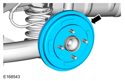
Remove the brake drum.
 |
-
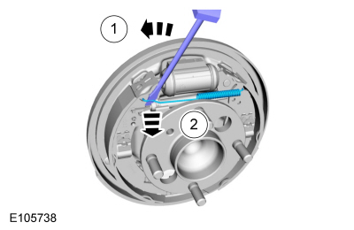
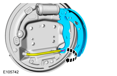
Using a screwdriver, detach and remove the upper return spring.
Use the General Equipment: Flat Headed Screw Driver
 |
-
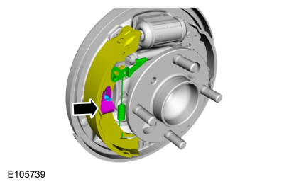
Remove the adjuster lever spring, the adjuster lever, the hold-down spring and the hold-down spring pin.
 |
-
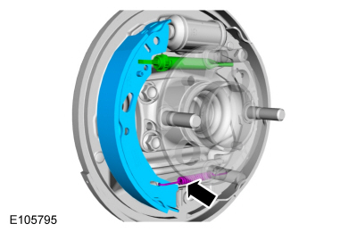
Remove the adjuster, the lower return spring and the brake shoe.
 |
-
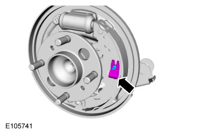
Remove the hold down spring and pin.
 |
-
Disconnect the parking brake cable from the lever and remove the brake shoe and lever assembly.
 |
Installation
-
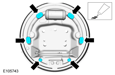
Using the specified grease, lubricate the brake shoe contact points.
Material: Motorcraft® Silicone Brake Caliper Grease and Dielectric Compound / XG-3-A (ESA-M1C200-A) (ESE-M1C171-A)
 |
-
To install, reverse the removal procedure.
-
NOTE: The brake shoes and parking brake cables must both be adjusted to assure correct rear drum brake and parking brake system operation.
Refer to: Parking Brake Cable Adjustment (206-05 Parking Brake and Actuation, General Procedures).
 Brake Backing Plate. Removal and Installation
Removal
NOTE:
Removal steps in this procedure may contain installation details.
Remove the brake shoes.
Refer to: Brake Shoes (206-02 Drum Brake, Removal and Installation)...
 Wheel Cylinder. Removal and Installation
Removal
NOTE:
Removal steps in this procedure may include installation details.
Refer to: Health and Safety Precautions (100-00 General Information, Description and Operation)...
Other information:
Ford Fiesta 2014 - 2019 Service Manual: Outer Constant Velocity (CV) Joint Boot. Removal and Installation
Special Tool(s) / General Equipment 205-343 (T95P-3514-A) Installer, Constant Velocity Joint Boot ClampTKIT-1995-FTKIT-1995-FM/FLMTKIT-1995-LM/M Materials Name Specification Motorcraft® Constant Velocity Joint GreaseXG-5 WSS-M1C258-A1 Removal Remove the inner CV joint boot...
Ford Fiesta 2014 - 2019 Service Manual: Fuel Lines. Removal and Installation
Removal NOTE: Removal steps in this procedure may contain installation details. Remove the Fuel Tank. Refer to: Fuel Tank (310-01B Fuel Tank and Lines - 1.6L EcoBoost (132kW/180PS) – Sigma, Removal and Installation). Remove the engine cover...
Categories
- Manuals Home
- Ford Fiesta Service Manual (2014 - 2019)
- Service Information
- Engine
- Front Suspension
- Engine - 1.6L EcoBoost (132kW/180PS) – Sigma
- Manual Transmission, Clutch, Transfer Case and Power Transfer Unit
Front Strut and Spring Assembly. Removal and Installation
Removal
NOTE: Removal steps in this procedure may contain installation details.
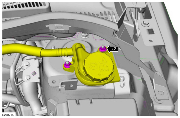
NOTE: This step is only necessary when installing a new component to the left-hand side.
Remove the nuts and position aside the remote brake fluid reservoir.Torque: 62 lb.in (7 Nm)
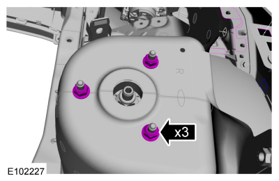
 Remove the strut and spring assembly upper mount nuts.
 Torque: 22 lb.ft (30 Nm)
Copyright © 2026 www.fofiesta7.com