Ford Fiesta: Engine System - General Information / Connecting Rod Bearing Journal Clearance. General Procedures
Ford Fiesta 2014 - 2019 Service Manual / Engine / Engine System - General Information / Connecting Rod Bearing Journal Clearance. General Procedures
Check
NOTE: Refer to the appropriate Section 303-01 for the specification.
-
NOTE: The crankshaft connecting rod journals must be within specifications to check the connecting rod bearing journal clearance.
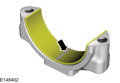
Remove the connecting rod bearing cap and connecting rod bearing.
-
Position a piece of Plastigage across the bearing surface.
 |
-
NOTE: Do not turn the crankshaft during this step.
Install and tighten to specifications, then remove the connecting rod bearing cap.
-
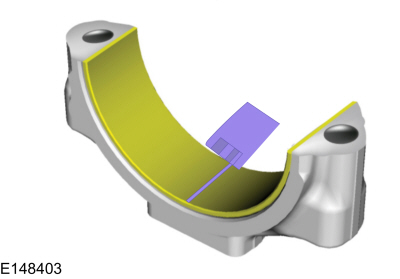
Measure the Plastigage to get the connecting rod bearing
journal clearance. The Plastigage should be smooth and flat. A changing
width indicates a tapered or damaged connecting rod or connecting rod
bearing.
 |

 Crankshaft Main Bearing Journal Clearance. General Procedures
Check
NOTE:
Refer to the appropriate Section 303-01 for the specification.
NOTE:
Crankshaft main bearing journals must be within specifications before checking journal clearance...
Other information:
Ford Fiesta 2014 - 2019 Service Manual: Brake Booster. Removal and Installation
Removal NOTE: Removal steps in this procedure may contain installation details. Remove the brake master cylinder. Refer to: Brake Master Cylinder (206-06 Hydraulic Brake Actuation, Removal and Installation). NOTICE: Do not service the brake pedal or brake booster without first removing the stoplamp switch...
Ford Fiesta 2014 - 2019 Service Manual: Piston Selection. General Procedures
Check NOTE: Refer to the appropriate Section 303-01 for the specifications. NOTE: The cylinder bore must be within the specifications for taper and out-of-round before fitting a piston. Measure the cylinder bore in 2 directions at 79...
Categories
- Manuals Home
- Ford Fiesta Service Manual (2014 - 2019)
- Engine - 1.6L EcoBoost (132kW/180PS) – Sigma
- Jacking and Lifting - Overview. Description and Operation
- Front Suspension
- Engine Component View. Description and Operation
- Engine. Assembly
Brake Master Cylinder. Removal and Installation
Removal
NOTICE: If the fluid is spilled on the paintwork, the affected area must be immediately washed down with cold water.
NOTE: Removal steps in this procedure may contain installation details.
All vehicles
Remove the battery tray.Refer to: Battery Tray - 1.6L Duratec-16V Ti-VCT (88kW/120PS) – Sigma (414-01 Battery, Mounting and Cables, Removal and Installation).
Refer to: Battery Tray - 1.6L EcoBoost (132kW/180PS) – Sigma (414-01 Battery, Mounting and Cables, Removal and Installation).
Disconnect the vacuum tube from the brake booster and detach the routing clip.
Copyright © 2026 www.fofiesta7.com