Ford Fiesta: Hydraulic Brake Actuation / Brake Pedal and Bracket. Removal and Installation
Removal
NOTICE: Do not service the brake pedal or brake booster without first removing the stoplamp switch and the cruise control deactivator switch. Remove the switches with the brake pedal in the at-rest position. The switch plunger must be compressed for the switch to rotate in the bracket. Removing the switches with the plunger extended (during pedal apply) will result in switch damage.
-
Remove the driver knee airbag.
Refer to: Driver Knee Airbag (501-20B Supplemental Restraint System, Removal and Installation).
-
Remove the stoplamp switch.
Refer to: Stoplamp Switch (417-01 Exterior Lighting, Removal and Installation).
-
Remove the Cruise Control Deactivator Switch.
Refer to: Cruise Control Deactivator Switch (419-03 Cruise Control, Removal and Installation).
-
Remove the accelerator pedal.
Refer to: Accelerator Pedal (310-02 Acceleration Control, Removal and Installation).
-
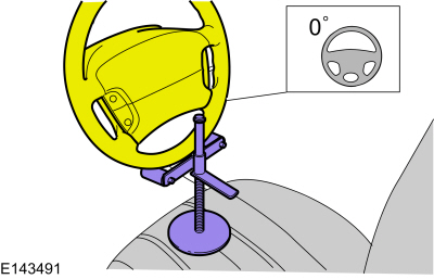
Secure the steering wheel using a steering wheel holding device.
 |
-
 WARNING:
Do not reuse steering column shaft bolts. This may
result in fastener failure and steering column shaft detachment or loss
of steering control. Failure to follow this instruction may result in
serious injury to vehicle occupant(s).
WARNING:
Do not reuse steering column shaft bolts. This may
result in fastener failure and steering column shaft detachment or loss
of steering control. Failure to follow this instruction may result in
serious injury to vehicle occupant(s).
NOTICE: Do not allow the steering column to rotate while the steering column shaft is disconnected or damage to the clockspring may result. If there is evidence that the steering column shaft has rotated, remove and re-center the clockspring. Refer to Section 501-20B.
Remove and discard the steering column shaft bolt.
Torque: 25 lb.ft (34 Nm)
 |
-
-
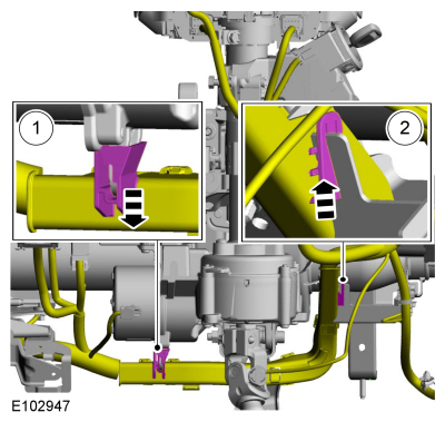
Detach the lower wiring harness retainer.
-
Detach the upper wiring harness retainer and position the wiring harness aside.
-
Detach the lower wiring harness retainer.
 |
-
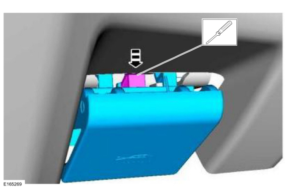
Depress the retaining tab and pull outward on the hood latch release handle.
 |
-
Remove the screws and position the DLC aside.
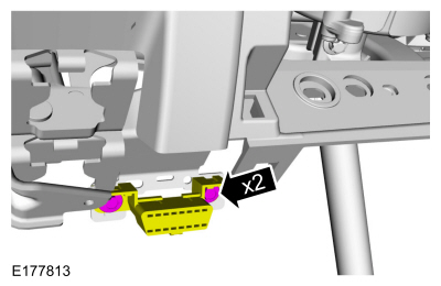 |
-
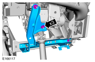
Remove the nuts and position the knee air bag bracket aside.
Torque: 71 lb.in (8 Nm)
 |
-
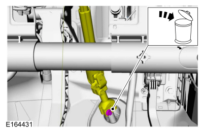
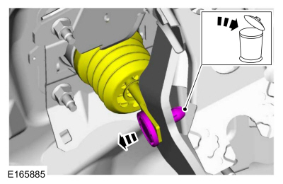
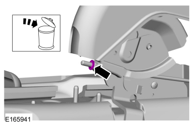
NOTE: The booster push rod clevis-locking pin is a one-time use only part. Any time the booster push rod clevis-locking pin is removed, a new booster push rod clevis-locking pin should be used.
Compress the tabs and remove the clevis pin. Discard the pin.
 |
-
Detach the wiring retainers and position the wiring aside.
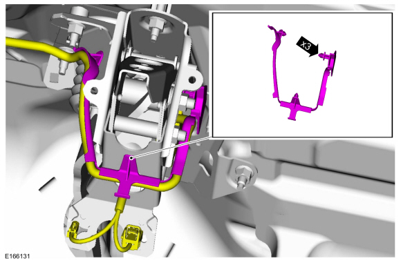 |
-
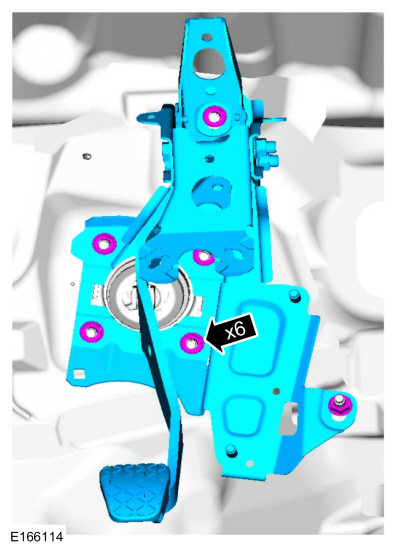
Remove the nuts and the brake pedal and bracket. Discard the nuts and bolts.
Torque: 18 lb.ft (25 Nm)
 |
Installation
-
NOTICE: Do not press, pull or otherwise move the brake pedal while installing the stoplamp switch and cruise control deactivator switch. Install these switches with the booster push rod attached to the brake pedal and with the brake pedal in the at-rest position. Installing these switches with the brake pedal in any other position will result in incorrect adjustment and may damage the switches.
To install, reverse the removal procedure.

 Brake Master Cylinder. Removal and Installation
Removal
NOTICE:
If the fluid is spilled on the paintwork, the affected area must be immediately washed down with cold water.
NOTE:
Removal steps in this procedure may contain installation details...
Other information:
Ford Fiesta 2014 - 2019 Service Manual: Specifications
General Specifications Item Specification Generator - 1.0L EcoBoost engine Generator pulley ratio 2.62:1 Rating 97 amps at 750 rpm (min) to 166 amps at 2,300 rpm (max) Voltage regulator type Electronic internal with generator Generator..
Ford Fiesta 2014 - 2019 Service Manual: Front Fog Lamp Bulb. Removal and Installation
Removal Remove the appropriate wheel and tire. Refer to: Wheel and Tire (204-04A Wheels and Tires, Removal and Installation). NOTE: If equipped with air dam extensions. Remove the screw and the pin-type retainer. NOTE: If equipped with air dam extensions. Remove the screws and the front stone def..
Categories
- Manuals Home
- Ford Fiesta Service Manual (2014 - 2019)
- Manual Transmission, Clutch, Transfer Case and Power Transfer Unit
- Fuel Pump. Removal and Installation
- Camshafts. Removal and Installation
- Engine System - General Information
- Lower Arm. Removal and Installation
Parking Brake Control. Removal and Installation
Removal
NOTE: Removal steps in this procedure may contain installation details.
Remove the floor console.Refer to: Floor Console (501-12 Instrument Panel and Console, Removal and Installation).
Remove the driver seat.
Refer to: Front Seat (501-10 Seating, Removal and Installation).
Remove the parking brake cable adjustment lock nut.
 Loosen the parking brake cable adjustment nut.