Ford Fiesta: Manual Transmission - 6-Speed Manual Transmission – B6 / Transmission. Removal
Special Tool(s) /
General Equipment
 |
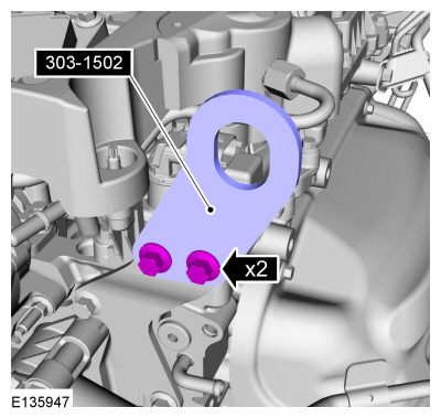
303-1502
Lifting Device Engine
TKIT-2012A-FL
TKIT-2012A-ROW |
 |
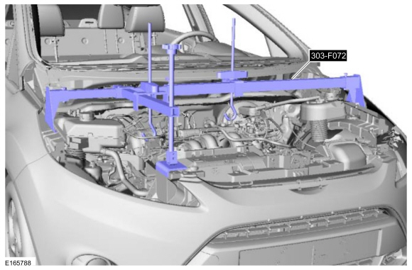
303-F072
Support Bar, Engine |
| Transmission Jack |
| Retaining Strap |
| Wooden Block |
-
If equipped.
Remove the engine appearance cover.
-
Remove the battery tray.
Refer to: Battery Tray - 1.6L EcoBoost (132kW/180PS) – Sigma (414-01 Battery, Mounting and Cables, Removal and Installation).
-
Detatch and position aside the wiring harness.
-
Remove the nuts and the battery tray bracket.
-
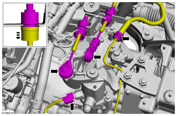
Disconnect the shift cable from the transmission and position aside.
-
Slide the locking tab and disconnect the gearshift cables from the transmission.
-
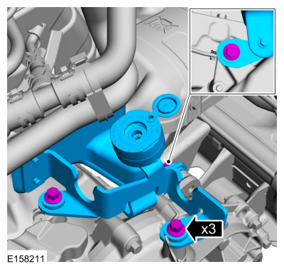
Remove the bolts and the gearshift cable bracket.
-
NOTE:
Note the different lengths of the bolts.
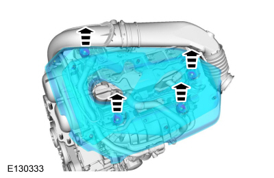
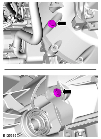
Remove the bellhousing bolts.
-
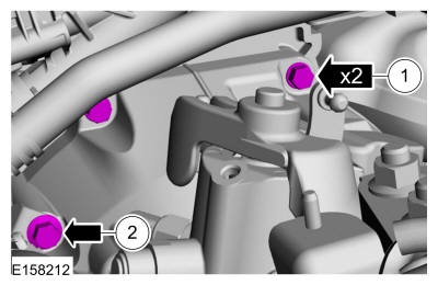
Remove the bolts, ground cable mounting and disconnect the wiring retainer.
-
Detatch the starter motor and position aside.
-
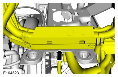
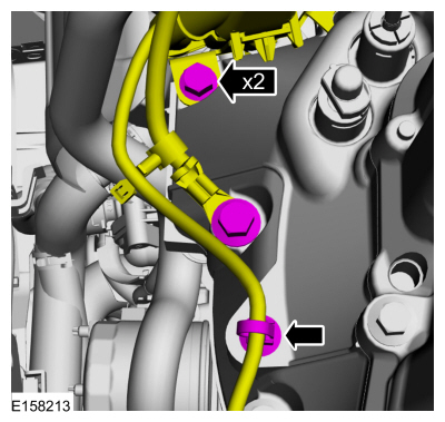
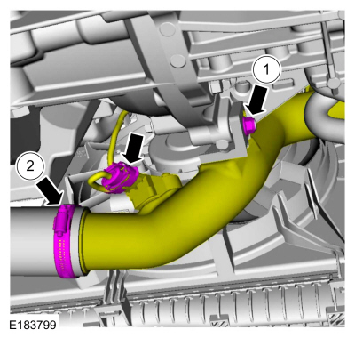
Disconnect the electrical connector and position aside the CAC outlet tube assembly.
-
Remove the nut.
-
Loosen the clamp.
-
Disconnect the electrical connector and position aside the hose.
-
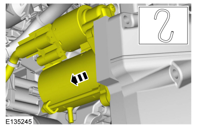
Remove the CAC inlet tube assembly.
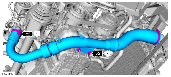
-
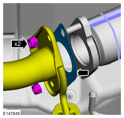
Loosen the clamps.
-
Remove the nuts.
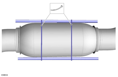
-
Support the exhaust flexible pipe with a support wrap or suitable splint.
-
Unhook the rear exhaust hanger isolator.
-
Remove and discard the muffler and tailpipe flange nuts and gasket.
-
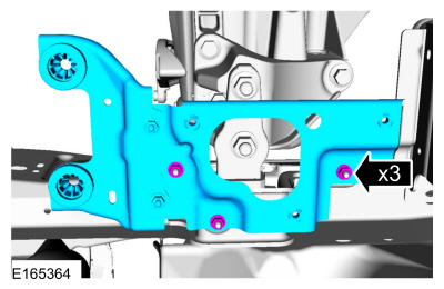
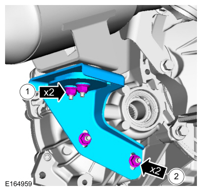
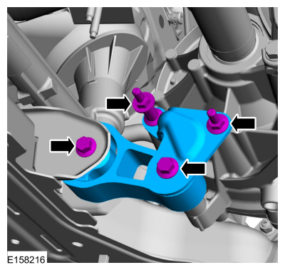
Remove the catalytic converter support bracket.
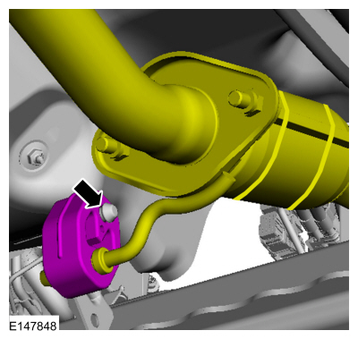
-
NOTE:
Note the different lengths of the bolts.
Remove the bolts and the roll restrictor RH .
-
Remove the front subframe.
Refer to: Front Subframe (502-00 Uni-Body, Subframe and Mounting System, Removal and Installation).
-
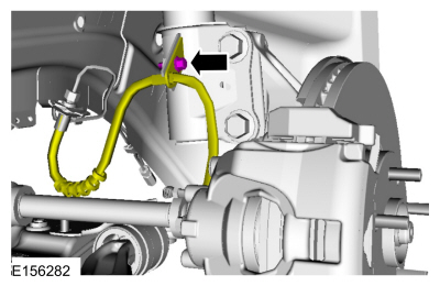
Remove the bolt and position aside the RH brake hose.
-
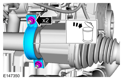
Remove and discard the halfshaft retaining strap and the halfshaft retaining strap nuts.
-
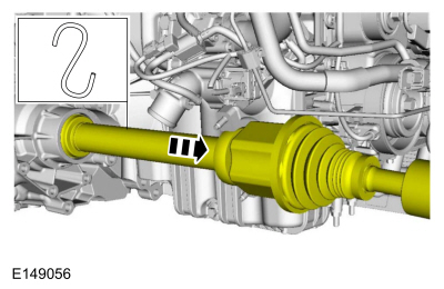
Remove and support the RH halfshaft from the transmission.
-
Remove the bolt and position aside the LH brake hose.
-
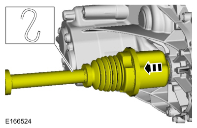
Remove and support the LH halfshaft from the transmission.
-
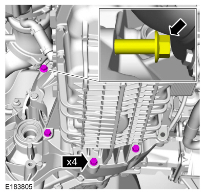
NOTE:
Note the different lengths of the bolts.
Remove the bellhousing bolts.
-
Remove the cowl panel.
Refer to: Cowl Panel (501-02 Front End Body Panels, Removal and Installation).
-
Install the special tool.
Use Special Service Tool: 303-1502
Lifting Device Engine.
-
Install the special tool and support the engine and transmission.
Use Special Service Tool: 303-F072
Support Bar, Engine.
-
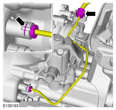
NOTICE:
Make sure that all openings are sealed.
Disconnect the clutch hydraulic tube.
-
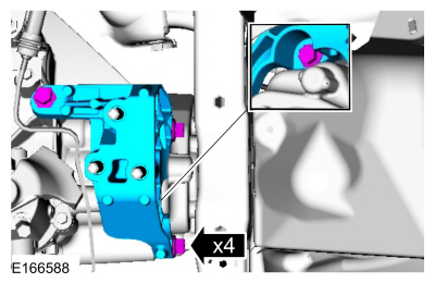
Remove the bolts, nuts and the transmission support insulator.
-
Remove the bolts and the transmission support insulator bracket.
-
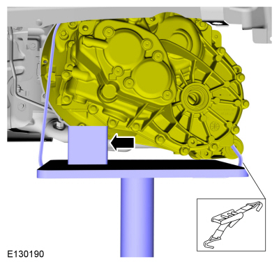
Install the following items:
-
Use the General Equipment: Transmission Jack
-
Use the General Equipment: Wooden Block
-
Use the General Equipment: Retaining Strap
-
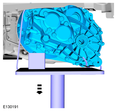
Remove the bellhousing bolts.
-
Remove the transmission.
Special Tool(s) /
General Equipment
Trolley Jack
Wooden Block
Removal
If equipped, remove the engine appearance cover...
Special Tool(s) /
General Equipment
307-003
(T57L-500-B)
Holding Fixture, Transmission
Puller
Punch
WARNING:
Before beginning any service procedure in this section, refer to
Safety Warnings in section 100-00 General Information...
Other information:
Special Tool(s) /
General Equipment
Hose Clamp Remover/Installer
Removal
With the vehicle in NEUTRAL, position it on a hoist.
Refer to: Jacking and Lifting - Overview (100-02 Jacking and Lifting, Description and Operation)...
Removal
NOTE:
Removal steps in this procedure may contain installation details.
Depower the SRS .
Refer to: Supplemental Restraint System (SRS) Depowering and Repowering
(501-20B Supplemental Restraint System, General Procedures)...
Categories
Preliminary Inspection
Verify the customer concern by carrying out a road test on a
smooth road. If any vibrations are apparent, Refer to the Symptom
Chart: NVH.
To maximize tire performance, inspect for signs of incorrect
inflation and uneven wear, which may indicate a need for balancing,
rotation or front suspension alignment.
Correct tire pressure and driving techniques have an
important influence on tire life. Heavy cornering, excessively rapid
acceleration and unnecessary sharp braking increase tire wear.
Correct
tire pressure and driving techniques have an important influence on
tire life. Heavy cornering, exce
read more

 Transmission Support Insulator. Removal and Installation
 Transmission. Disassembly