
Ford Fiesta: Manual Transmission - 6-Speed Manual Transmission – B6 / Transmission Support Insulator. Removal and Installation
Ford Fiesta 2014 - 2019 Service Manual / Manual Transmission, Clutch, Transfer Case and Power Transfer Unit / Manual Transmission - 6-Speed Manual Transmission – B6 / Transmission Support Insulator. Removal and Installation
Special Tool(s) / General Equipment
| Trolley Jack | |
| Wooden Block |
Removal
-
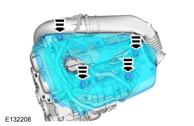
If equipped, remove the engine appearance cover.
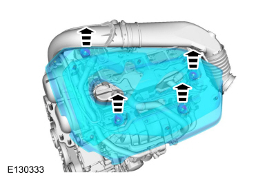 |
-
Remove the battery tray.
Refer to: Battery Tray - 1.6L EcoBoost (132kW/180PS) – Sigma (414-01 Battery, Mounting and Cables, Removal and Installation).
-
Disconnect the wiring retainers from the battery tray support bracket and position the wiring aside.
 |
-
Remove the nuts and the battery tray support bracket.
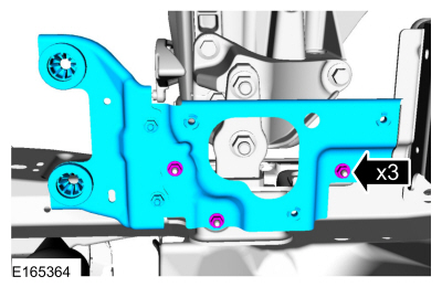 |
-
Support the transmission.
Use the General Equipment: Trolley Jack
Use the General Equipment: Wooden Block
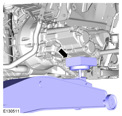 |
-
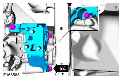
Remove the bolts and the nuts and remove the transmission support insulator.
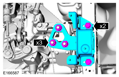 |
-
If required, remove the bolts and remove the transmission support insulator bracket.
 |
Installation
-
Install the transmission support insulator bracket and install the bolts.
Torque: 59 lb.ft (80 Nm)
|
-
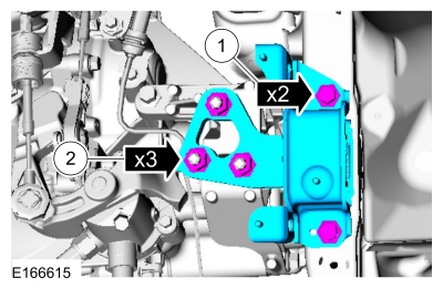
Install the transmission support insulator, install the bolts and the nuts.
Torque:
1: 66 lb.ft (90 Nm)
2: 92 lb.ft (125 Nm)
 |
-
Install the battery tray support bracket and install the nuts.
Torque: 89 lb.in (10 Nm)
|
-
Install the wiring retainers on the battery tray support bracket.
|
-
Install the battery tray.
Refer to: Battery Tray - 1.6L EcoBoost (132kW/180PS) – Sigma (414-01 Battery, Mounting and Cables, Removal and Installation).
-
If equipped, install the engine appearance cover.
 |
 Roll Restrictor RH. Removal and Installation
Removal
With the vehicle in N , position it on a hoist.
Refer to: Jacking and Lifting - Overview (100-02 Jacking and Lifting, Description and Operation)...
 Transmission. Removal
Special Tool(s) /
General Equipment
303-1502Lifting Device EngineTKIT-2012A-FLTKIT-2012A-ROW
303-F072Support Bar, Engine
Transmission Jack
Retaining Strap
Wooden Block
If equipped...
Other information:
Ford Fiesta 2014 - 2019 Service Manual: Air Cleaner Outlet Pipe. Removal and Installation
Removal NOTE: Removal steps in this procedure may contain installation details. Disconnect and position aside the vent tube. Loosen the clamps and remove the air cleaner outlet pipe. Torque: 44 lb.in (5 Nm) Installation To install, reverse the removal procedure...
Ford Fiesta 2014 - 2019 Service Manual: Welding Precautions. General Procedures
Check WARNING: Invisible ultraviolet and infrared rays emitted in welding can injure unprotected eyes and skin. Always use protection such as a welder's helmet with dark-colored filter lenses of the correct density. Electric welding will produce intense radiation, therefore, filter plate lenses of the deepest shade providing adequate visibility are recommended...
Categories
- Manuals Home
- Ford Fiesta Service Manual (2014 - 2019)
- Engine Cooling - 1.6L EcoBoost (132kW/180PS) – Sigma
- Front Suspension
- Maintenance Schedules
- Manual Transmission - 6-Speed Manual Transmission – B6
- Jacking and Lifting - Overview. Description and Operation
Brake Backing Plate. Removal and Installation
Removal
NOTE: Removal steps in this procedure may contain installation details.
Remove the brake shoes.Refer to: Brake Shoes (206-02 Drum Brake, Removal and Installation).
Disconnect the brake tube fitting.
Torque: 159 lb.in (18 Nm) Remove the bolt and wheel cylinder.
Torque: 106 lb.in (12 Nm)
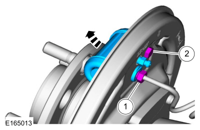 Disconnect the brake shoe lever fitting and re

Copyright © 2026 www.fofiesta7.com