
Ford Fiesta: Manual Transmission - 6-Speed Manual Transmission – B6 / Transmission Draining and Filling. General Procedures
Ford Fiesta 2014 - 2019 Service Manual / Manual Transmission, Clutch, Transfer Case and Power Transfer Unit / Manual Transmission - 6-Speed Manual Transmission – B6 / Transmission Draining and Filling. General Procedures
Materials
| Name | Specification |
|---|---|
| Motorcraft® Dual Clutch Transmission Fluid XT-11-QDC |
WSS-M2C200-D2 |
Draining
-
With the vehicle in N , position it on a hoist.
Refer to: Jacking and Lifting - Overview (100-02 Jacking and Lifting, Description and Operation).
-
If equipped.
Remove the retainers and the underbody shield.
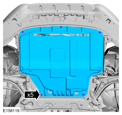 |
-
Remove the drain plug and drain the transmission fluid.
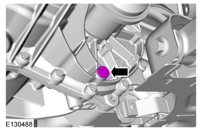 |
-
Install the drain plug.
Torque: 30 lb.ft (40 Nm)
|
Filling
-
Remove the fill plug.
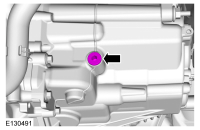 |
-
Fill the transmission.
Material: Motorcraft® Dual Clutch Transmission Fluid / XT-11-QDC (WSS-M2C200-D2)
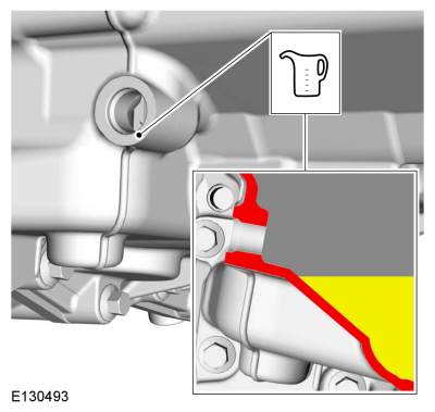 |
-
NOTE: Remove enough fluid to be 1 in ( 20 mm) below fill hole.
Remove enough fluid to be 1 in (20 mm) below fill hole.
 |
-
Install the fill plug.
Torque: 30 lb.ft (40 Nm)
|
-
If equipped.
Install the underbody shield.
|
 Transmission Fluid Level Check. General Procedures
Materials
Name
Specification
Motorcraft® Dual Clutch Transmission FluidXT-11-QDC
WSS-M2C200-D2
Check
With the vehicle in N , position it on a hoist...
 3rd-4th Gear Synchronizer. Removal and Installation
Special Tool(s) /
General Equipment
205-199
(T83T-3132-A1)
Installer, Spindle/Axle ShaftT83-4000-ATKIT-1983-FTKIT-1983-FLMTKIT-1983-FX
205-D015
(D80L-630-4)
Step Plate
211-014Remover, Steering Wheel
307-003
(T57L-500-B)
Holding Fixture, Transmission
307-680Table, Assembly (DPS6)TKIT-2010D-FLMTKIT-2010D-ROW
308-847Instal..
Other information:
Ford Fiesta 2014 - 2019 Service Manual: Pinpoint Test - DTC: GG. Diagnosis and Testing
B0061:11, B0061:12, B0061:13, B0061:64 Refer to Wiring Diagrams Cell 46 for schematic and connector information. Normal Operation and Fault Conditions The Belt Tension Sensor (BTS) operates in conjunction with the OCS . The OCS interprets a variable voltage signal provided by the Belt Tension Sensor (BTS) to identify the possible presence of a child safety seat in the front pa..
Ford Fiesta 2014 - 2019 Service Manual: Valve Guide Inner Diameter. General Procedures
Check NOTE: Refer to the appropriate Section 303-01 for the specification. NOTE: Valve guides tend to wear in an hourglass pattern. The ball gauge can be inserted into the combustion chamber side of the valve guide, if necessary. Use a ball gauge to determine the inside diameter of the valve guides in 2 directions at the top, middle and bottom of the val..
Categories
- Manuals Home
- Ford Fiesta Service Manual (2014 - 2019)
- Cylinder Head. Removal and Installation
- Engine System - General Information
- Jacking and Lifting - Overview. Description and Operation
- Brake System
- Engine - 1.6L EcoBoost (132kW/180PS) – Sigma
Axle. Removal and Installation
Special Tool(s) / General Equipment
Flat Headed Screw Driver Transmission Jack Vehicle/Axle StandsRemoval
NOTICE: Suspension fasteners are critical parts that affect performance of vital components and systems. Failure of these fasteners may result in major service expense. Use the same or equivalent parts if replacement is necessary. Do not use a replacement part of lesser quality or substitute design. Tighten fasteners as specified.
Remove the floor console.Refer to: Floor Console (501-12 Instrum

Copyright © 2026 www.fofiesta7.com