Ford Fiesta: Supplemental Restraint System / Pinpoint Test - DTC: GG. Diagnosis and Testing
B0061:11, B0061:12, B0061:13, B0061:64
Refer to Wiring Diagrams Cell 46 for schematic and connector information.
Normal Operation and Fault Conditions
The Belt Tension Sensor (BTS) operates in conjunction with the OCS . The OCS interprets a variable voltage signal provided by the Belt Tension Sensor (BTS) to identify the possible presence of a child safety seat in the front passenger seat. The voltage output of the Belt Tension Sensor (BTS) is proportional to the amount of tension applied to the sensor by the belt: no belt tension causes a low voltage (approximately 0.95 volt) to be output and high belt tension causes a high voltage (approximately 3.8 volts) to be returned to the OCSM .
The OCSM monitors the Belt Tension Sensor (BTS) and related circuits for the following faults:
- Resistance out of range
- Unexpected voltage
- Short to ground
- Faulted Belt Tension Sensor (BTS) (part of RH front passenger seatbelt buckle)
If a fault is detected, the OCSM stores DTC B0061:11, B0061:12, B0061:13 or B0061:64 in memory and sends a message to the RCM over the HS-CAN2 indicating that an OCSM fault is present. Upon receipt of this message, the RCM sets DTC B00A0:09 and sends a message to the IPC to illuminate the airbag warning indicator.
DTC Fault Trigger Conditions
| DTC | Description | Fault Trigger Conditions |
|---|---|---|
| B0061:11 | Passenger Seatbelt Tension Sensor: Circuit Short to Ground | A fault is indicated when the OCSM measures voltage below a predetermined threshold on the Belt Tension Sensor (BTS) signal circuit. An open Belt Tension Sensor (BTS) VREF circuit can also set this DTC . |
| B0061:12 | Passenger Seatbelt Tension Sensor: Circuit Short to Battery | A fault is indicated when the OCSM measures voltage above a predetermined threshold on the Belt Tension Sensor (BTS) signal circuit. An open Belt Tension Sensor (BTS) return circuit can also set this DTC . |
| B0061:13 | Passenger Seatbelt Tension Sensor: Circuit Open | A fault is indicated when the OCSM senses an open on either Belt Tension Sensor (BTS) circuit. |
| B0061:64 | Passenger Seatbelt Tension Sensor: Signal Plausibility Failure | A fault is indicated when the passenger seatbelt is unbuckled and the OCSM measures voltage on the Belt Tension Sensor (BTS) signal circuit greater than the maximum voltage returned during normal sensor operation. |
Possible Sources
- Wiring, terminals or connectors
- Belt Tension Sensor (BTS) (part of RH front passenger seatbelt buckle)
- OCSM
Visual Inspection and Diagnostic Pre-checks
- Inspect for a damaged passenger seatbelt buckle or Belt Tension Sensor (BTS).
- Inspect for a damaged passenger seat cushion wiring harness.
- Inspect for a loose or damaged OCSM or Belt Tension Sensor (BTS) connector.
- Inspect for a damaged OCSM .
PINPOINT TEST A: B0061:11, B0061:12, B0061:13, B0061:64
| NOTE: Most faults are due to connector and/or wiring concerns. Carry out a thorough inspection and verification before proceeding with the pinpoint test. | |||||||||||||||||||
| NOTE: Only disconnect or reconnect SRS components when instructed to do so within a pinpoint test step. Failure to follow this instruction may result in incorrect diagnosis of the SRS . | |||||||||||||||||||
| NOTE: Always make sure the correct SRS component is being installed. Parts released for other vehicles may not be compatible even if they appear physically similar. Check the part number listed in the Ford parts catalog to make sure the correct component is being installed. If an incorrect SRS component is installed, Diagnostic Trouble Codes (DTCs) may set. | |||||||||||||||||||
| NOTE: The SRS must be fully operational and free of faults before releasing the vehicle to the customer. | |||||||||||||||||||
| A1 RETRIEVE OCSM (OCCUPANT CLASSIFICATION SYSTEM MODULE) DIAGNOSTIC TROUBLE CODES (DTCS) | |||||||||||||||||||
Was DTC B0061:11, B0061:12, B0061:13 or B0061:64 retrieved on-demand during self-test?
|
|||||||||||||||||||
| A2 CHECK THE BELT TENSION SENSOR (BTS) | |||||||||||||||||||
|
NOTE: This pinpoint test step attempts to change the fault reported by the OCSM by inducing a different fault condition. If the fault reported changes, this indicates the OCSM is functioning correctly and is not the source of the fault.
Was DTC B0061:11 retrieved on-demand during self-test?
|
|||||||||||||||||||
| A3 CHECK THE BELT TENSION SENSOR (BTS) CIRCUITS FOR A SHORT TO GROUND OR A SHORT TOGETHER | |||||||||||||||||||
|
Are the resistances greater than 10,000 ohms?
|
|||||||||||||||||||
| A4 CHECK THE BELT TENSION SENSOR (BTS) VREF CIRCUIT FOR AN OPEN | |||||||||||||||||||
Is the resistance less than 0.5 ohm?
|
|||||||||||||||||||
| A5 CHECK THE BELT TENSION SENSOR (BTS) SIGNAL CIRCUIT FOR A SHORT TO VOLTAGE | |||||||||||||||||||
Is any voltage present?
|
|||||||||||||||||||
| A6 CHECK THE BELT TENSION SENSOR (BTS) GROUND CIRCUIT FOR AN OPEN | |||||||||||||||||||
Is the resistance less than 3 ohms?
|
|||||||||||||||||||
| A7 CHECK THE BELT TENSION SENSOR (BTS) | |||||||||||||||||||
|
NOTE: This pinpoint test step attempts to change the fault reported by the OCSM by inducing a different fault condition. If the fault reported changes, this indicates the OCSM is functioning correctly and is not the source of the fault.
Did the on-demand DTC change from B0061:13 to B0061:11?
|
|||||||||||||||||||
| A8 CHECK THE BELT TENSION SENSOR (BTS) SIGNAL CIRCUIT FOR AN OPEN | |||||||||||||||||||
Is the resistance less than 0.5 ohm?
|
|||||||||||||||||||
| A9 CHECK THE BELT TENSION SENSOR (BTS) SIGNAL CIRCUIT FOR A SHORT TO THE BELT TENSION SENSOR (BTS) VREF CIRCUIT | |||||||||||||||||||
|
Is the resistance greater than 10,000 ohms?
|
|||||||||||||||||||
| A10 CHECK BELT TENSION SENSOR (BTS) VOLTAGE OUTPUT | |||||||||||||||||||
Does the voltage vary from approximately 0.95 volt with no tension applied to the sensor to approximately 3.8 volts with full tension applied to the sensor?
|
|||||||||||||||||||
| A11 CONFIRM THE OCSM (OCCUPANT CLASSIFICATION SYSTEM MODULE) FAULT | |||||||||||||||||||
|
NOTE: Make sure all OCS components, SRS electrical connectors and the RCM electrical connectors are connected before carrying out the self-test. If not, Diagnostic Trouble Codes (DTCs) will be recorded.
Was the original DTC retrieved on-demand during self-test?
|
|||||||||||||||||||
| A12 CHECK FOR AN INTERMITTENT FAULT | |||||||||||||||||||
|
Was DTC B0061:11, B0061:12, B0061:13 or B0061:64 retrieved on-demand during self-test?
|
|||||||||||||||||||
| A13 CHECK FOR ADDITIONAL SRS (SUPPLEMENTAL RESTRAINT SYSTEM) DIAGNOSTIC TROUBLE CODES (DTCS) | |||||||||||||||||||
|
Are any RCM , OCSM and/or BECMB Diagnostic Trouble Codes (DTCs) retrieved on-demand during self-test?
|
 WARNING:
Before beginning any service procedure in this
section, refer to Safety Warnings in section 100-00 General Information.
Failure to follow this instruction may result in serious personal
injury.
WARNING:
Before beginning any service procedure in this
section, refer to Safety Warnings in section 100-00 General Information.
Failure to follow this instruction may result in serious personal
injury.


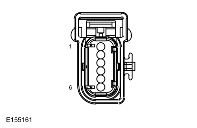 C3238, pin 3, harness side
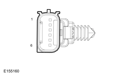 C3238, pin 3, component side
 Pinpoint Test - DTC: FF. Diagnosis and Testing
U3003:16 and U3003:17
Refer to Wiring Diagrams Cell 46 for schematic and connector information.
NOTE:
Diagnostic Trouble Codes (DTCs) U3003:16 and U3003:17 can
be set if the vehicle has been recently jump started, the battery has
been recently charged or the battery has been discharged...
 Pinpoint Test - DTC: HH. Diagnosis and Testing
B00C2:11 and B00C2:12
Refer to Wiring Diagrams Cell 46 for schematic and connector information.
Normal Operation and Fault Conditions
The Belt Tension Sensor (BTS) operates in conjunction with the OCS ...
Other information:
Ford Fiesta 2014 - 2019 Service Manual: Pinpoint Test - DTC: V. Diagnosis and Testing
B1415:11, B1415:93, B1418:11 and B1418:93 Refer to Wiring Diagrams Cell 46 for schematic and connector information. Normal Operation and Fault Conditions The RCM monitors the passenger front door and LH C-pillar side impact sensors and circuits for the following faults: Open circuit Short to voltage Short to ground Faulted passenger fr..
Ford Fiesta 2014 - 2019 Service Manual: Headlamp Assembly. Removal and Installation
Removal NOTE: Removal steps in this procedure may contain installation details. Disconnect the headlamp electrical connector. Remove the bolt and remove the headlamp assembly. Torque: 44 lb.in (5 Nm) Installation To install, reverse the removal procedure. ..
Categories
- Manuals Home
- Ford Fiesta Service Manual (2014 - 2019)
- Front Suspension
- Engine - 1.6L EcoBoost (132kW/180PS) – Sigma
- Engine Cooling - 1.6L EcoBoost (132kW/180PS) – Sigma
- Clutch - 6-Speed Manual Transmission – B6
- Timing Belt. Removal and Installation
Brake Drum. Removal and Installation
Removal
NOTE: Removal steps in this procedure may contain installation details.
 WARNING:
Before beginning any service procedure in this
manual, refer to health and safety warnings in section 100-00 General
Information. Failure to follow this instruction may result in serious
personal injury.
WARNING:
Before beginning any service procedure in this
manual, refer to health and safety warnings in section 100-00 General
Information. Failure to follow this instruction may result in serious
personal injury.
Remove the wheel and tire.
Refer to: Wheel and Tire (204-04A Wheels and Tires, Removal and Installation).