Ford Fiesta: Wiring Harnesses / Transmission Control Module (TCM) Wiring Harness. Removal and Installation
Special Tool(s) /
General Equipment
Removal
NOTE:
Removal steps in this procedure may contain installation details.
-
Remove the battery tray.
Refer to: Battery Tray - 1.6L EcoBoost (132kW/180PS) – Sigma (414-01 Battery, Mounting and Cables, Removal and Installation).
Refer to: Battery Tray - 1.6L EcoBoost (132kW/180PS) – Sigma (414-01 Battery, Mounting and Cables, Removal and Installation).
-
-
Disconnect the retainers from the battery tray support bracket and position aside the wiring harness.
-
Remove the nut and position aside the ground cable.
Torque:
89 lb.in (10 Nm)
-
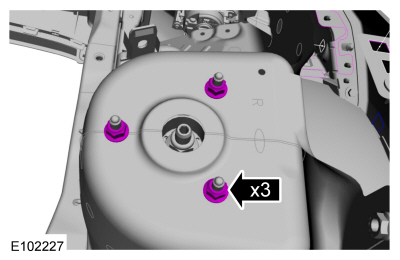
Remove the nuts and remove the battery tray support bracket.
Torque:
18 lb.ft (25 Nm)
-
-
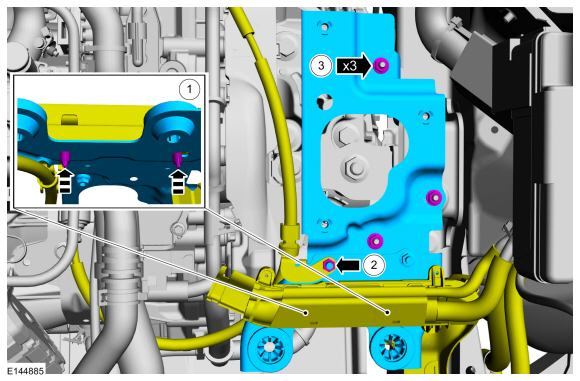
Remove the wiring bracket bolt.
-
Pull the wiring bracket up to release the retainer.
Vehicles with 1.0L engine
-
Remove the shift cable from the retainer.
All vehicles
-
NOTICE:
Take extra care not to damage the wiring harnesses.
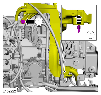
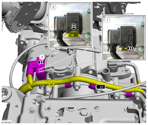
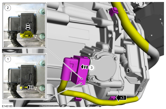
Disconnect the clutch actuator motor A electrical connector.
-
Unlock the electrical connector.
-
Push the electrical connector lock outward.
-
Disconnect the clutch actuator motor A electrical connector.
-
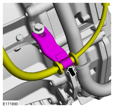
Disconnect the wiring harness retainers.
-
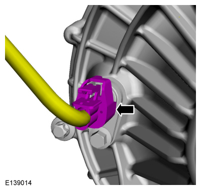
Disconnect the TR sensor electrical connector.
-
With the vehicle in NEUTRAL, position it on a hoist.
Refer to: Jacking and Lifting - Overview (100-02 Jacking and Lifting, Description and Operation).
-
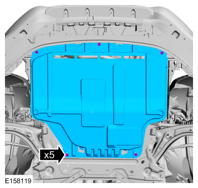
If equipped.
Remove the retainers and the underbody shield.
-
-
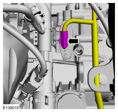
Disconnect the ISS sensor B electrical connector.
-
Disconnect the ISS sensor A electrical connector.
-
Disconnect the wiring harness retainer and position aside the wiring harness.
-
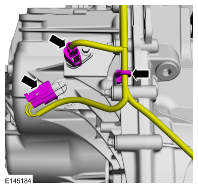
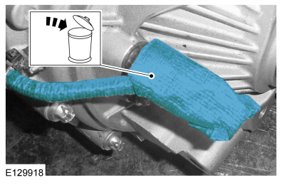
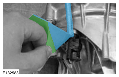
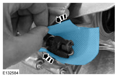
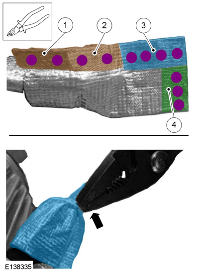
Remove and discard the foil tape from the OSS sensor electrical connector and wiring harness.
-
Disconnect the OSS sensor electrical connector.
-
Disconnect the clutch actuator motor B electrical connector.
-
Unlock the electrical connector.
-
Push the electrical connector lock outward.
-
Disconnect the clutch actuator motor B electrical connector.
-
Disconnect the wiring harness retainers.
-
NOTICE:
Make sure that the terminals or pins/sockets of
the transmission control module (TCM) and the TCM electrical connector
are not bent or damaged.
Disconnect the TCM electrical connector, the wiring harness retainers and remove the TCM wiring harness.
Installation
-
Connect the OSS sensor electrical connector.
-
NOTICE:
Make sure that the surface is clean and free of foreign material before taping around the component.
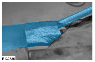
Remove the foil tape backing and wrap the foil tape around the OSS sensor wiring harness.
-
Remove the foil tape backing from the rest of the foil tape.
-
Wrap the foil tape around the OSS sensor electrical connector.
-
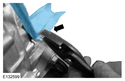
Stick the foil tape ends together.
-
Using the locking plier, crimp around the edge starting from the sensor portion.
Use the General Equipment: Locking Pliers
-
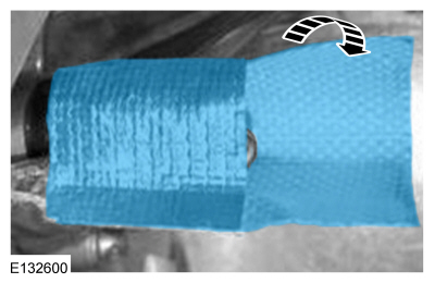
Fold the remaining portion of the foil tape.
-
Using the locking plier, crimp around the edge starting from the sensor portion moving around.
Use the General Equipment: Locking Pliers
-
To install, reverse the removal procedure.
Other information:
System Operation
Emergency Locking Retractor (ELR)
All
retractors have an Emergency Locking Retractor (ELR) mode, which is a
vehicle-sensitive feature designed to activate and lock the safety belt
webbing during hard braking, cornering, or an impact of approximately 24
km/h (14.9 mph). The Emergency Locking Retractor (ELR) feature helps
reduce the forward movement of the driver..
Removal
Release the retaining tabs and remove the glove compartment.
Release the retaining tabs and remove the instrument
panel passenger side finish panel. Disconnect the electrical connector.
Installation
To install, reverse the removal procedure.
..


 Remove the strut and spring assembly upper mount nuts.