Ford Fiesta: Interior Trim and Ornamentation / Rear Door Trim Panel. Removal and Installation
Ford Fiesta 2014 - 2019 Service Manual / Body and Paint / Interior Trim and Ornamentation / Rear Door Trim Panel. Removal and Installation
Special Tool(s) / General Equipment
| Pick Hook | |
| Interior Trim Remover |
Removal
-
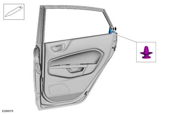
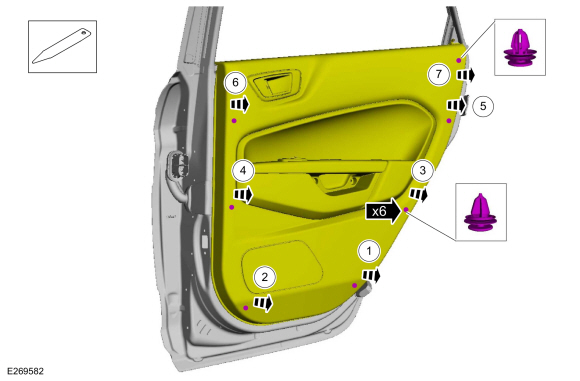
Release the clip and remove the rear door sail panel.
Use the General Equipment: Interior Trim Remover
 |
-
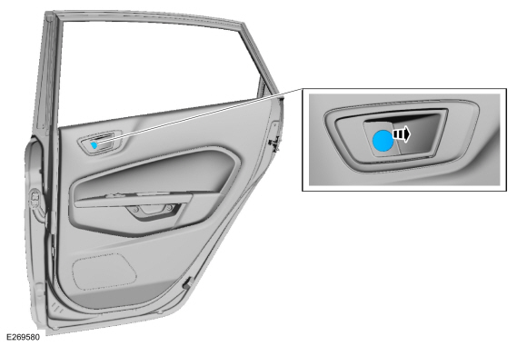
Remove the interior door handle screw cover.
Use the General Equipment: Pick Hook
 |
-
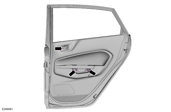
Remove the rear door trim panel screws.
 |
Vehicles with manual windows
-
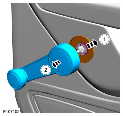
Remove the window regulator handle.
-
Remove the retaining clip.
-
Remove the window regulator handle and the spacer.
-
Remove the retaining clip.
 |
All vehicles
-
Release the rear door trim panel clips in the following sequence.
-
Release the lower RH rear door trim panel clip.
Use the General Equipment: Interior Trim Remover
-
Release the lower LH rear door trim panel clip.
Use the General Equipment: Interior Trim Remover
-
Release the RH middle rear door trim panel clip.
Use the General Equipment: Interior Trim Remover
-
Release the LH middle rear door trim clip.
Use the General Equipment: Interior Trim Remover
-
Release the RH rear door trim panel clip.
Use the General Equipment: Interior Trim Remover
-
Release the LH upper rear door trim panel clip.
Use the General Equipment: Interior Trim Remover
-
Release the RH upper rear door trim panel clip.
Use the General Equipment: Interior Trim Remover
-
Release the lower RH rear door trim panel clip.
 |
-
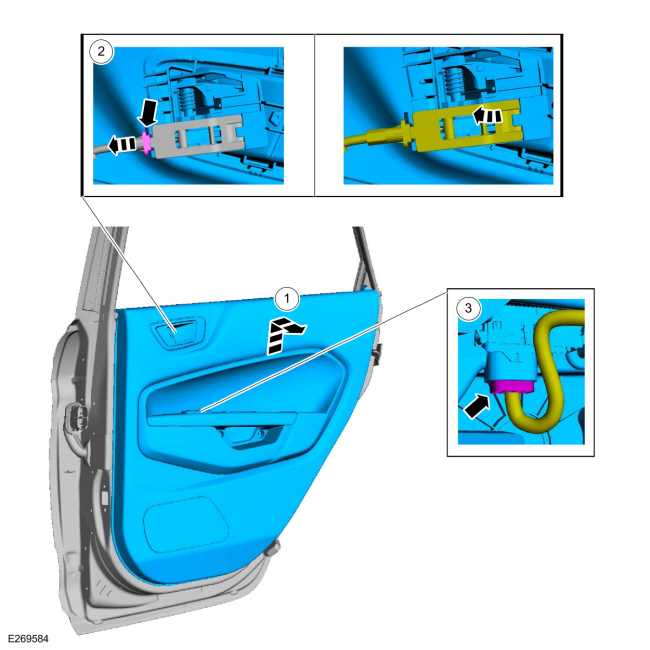
Remove the rear door trim panel.
-
Lift upward and outward on the rear door trim panel.
-
Release the tab and disconnect the rear door latch cable.
-
If equipped.
Disconnect the rear door window control switch electrical connector.
-
Lift upward and outward on the rear door trim panel.
 |
Installation
-
To install, reverse the removal procedure
 A-Pillar Trim Panel. Removal and Installation
Removal
NOTE:
Removal steps in this procedure may contain installation details.
NOTE:
LH shown, RH similar.
Position the front door weatherstrip aside...
 Liftgate Trim Panel. Removal and Installation
Removal
NOTE:
Removal steps in this procedure may contain installation details.
Release the clips and remove the LH upper side trim panel...
Other information:
Ford Fiesta 2014 - 2019 Service Manual: Brake Backing Plate. Removal and Installation
Removal NOTE: Removal steps in this procedure may contain installation details. Remove the brake shoes. Refer to: Brake Shoes (206-02 Drum Brake, Removal and Installation). Disconnect the brake tube fitting...
Ford Fiesta 2014 - 2019 Service Manual: Specifications
Torque Specifications Item Nm lb-ft lb-in Halfshaft support bracket bolts - 1.6L Duratec-16V Ti-VCT (M8 X 1.25) (2) 24 18 216 Halfshaft support bracket bolt - 1...
Categories
- Manuals Home
- Ford Fiesta Service Manual (2014 - 2019)
- Clutch - 6-Speed Manual Transmission – B6
- Engine. Assembly
- Engine Cooling - 1.6L EcoBoost (132kW/180PS) – Sigma
- Fuel Pump. Removal and Installation
- Manual Transmission, Clutch, Transfer Case and Power Transfer Unit
Component Bleeding. General Procedures
Special Tool(s) / General Equipment
Master Cylinder Bleeding SetBleeding
NOTICE: If the fluid is spilled on the paintwork, the affected area must be immediately washed down with cold water.
Master Cylinder
NOTE: When a new brake master cylinder has been installed, it should be primed to prevent air from entering the system.
NOTE: Make sure the area around the master cylinder cap is clean and free of foreign material.
Remove the brake fluid reservoir cap.Copyright © 2026 www.fofiesta7.com