Ford Fiesta: Front Drive Halfshafts / Outer Constant Velocity (CV) Joint Boot. Removal and Installation
Ford Fiesta 2014 - 2019 Service Manual / Driveline / Front Drive Halfshafts / Outer Constant Velocity (CV) Joint Boot. Removal and Installation
Special Tool(s) / General Equipment
 |
205-343
(T95P-3514-A)
Installer, Constant Velocity Joint Boot Clamp TKIT-1995-F TKIT-1995-FM/FLM TKIT-1995-LM/M |
Materials
| Name | Specification |
|---|---|
| Motorcraft® Constant Velocity Joint Grease XG-5 |
WSS-M1C258-A1 |
Removal
-
Remove the inner CV joint boot.
Refer to: Inner Constant Velocity (CV) Joint Boot (205-04 Front Drive Halfshafts, Removal and Installation).
-
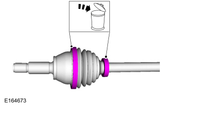
Remove and discard the CV joint boot clamps.
 |
-
Remove the outer CV joint boot.
 |
Installation
-
NOTE: Grease sachet is supplied with boot kit.
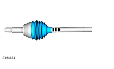
Install the outer CV boot and apply grease to the inside of CV boot.
Material: Motorcraft® Constant Velocity Joint Grease / XG-5 (WSS-M1C258-A1)
 |
-
NOTE: Grease sachet is supplied with boot kit.
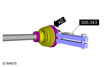
Using the special tool, install the new CV boot clamps.
Use Special Service Tool: 205-343 (T95P-3514-A) Installer, Constant Velocity Joint Boot Clamp.
 |
-
Install the inner CV joint boot.
Refer to: Inner Constant Velocity (CV) Joint Boot (205-04 Front Drive Halfshafts, Removal and Installation).

 Halfshaft Bearing - 1.6L EcoBoost (132kW/180PS) – Sigma. Removal and Installation
Special Tool(s) /
General Equipment
205-343
(T95P-3514-A)
Installer, Constant Velocity Joint Boot ClampTKIT-1995-FTKIT-1995-FM/FLMTKIT-1995-LM/M
205-D064
(D84L-1123-A)
Puller, Bearing
Flat Headed Screw Driver
Hydraulic Press
Materials
Name
Specification
Motorcraft® Constant Velocity Joint GreaseXG-5
WSS-M1C258-A1
..
Other information:
Ford Fiesta 2014 - 2019 Service Manual: Reverse Gear Output Shaft. Disassembly and Assembly of Subassemblies
Special Tool(s) / General Equipment 205-D015 (D80L-630-4) Step Plate 205-D016 (D80L-630-5) Step Plate 307-679Installer, Countershaft Needle BearingTKIT-2010D-FLMTKIT-2010D-ROW 308-416Remover/Installer, Thrust Washer Bearing CupTKIT-1999A-F/LTTKIT-1999A-FM/FLM Hydraulic Press Puller Bearing Separator Materials ..
Ford Fiesta 2014 - 2019 Service Manual: Headlamps. Diagnosis and Testing
DTC Chart: BCM Diagnostics in this manual assume a certain skill level and knowledge of Ford-specific diagnostic practices. REFER to: Diagnostic Methods (100-00 General Information, Description and Operation). BCM DTC Chart DTC Description Action B1007:92 High-Beam Head..
Categories
- Manuals Home
- Ford Fiesta Service Manual (2014 - 2019)
- Service Information
- Front Suspension
- Cylinder Head. Removal and Installation
- Maintenance Schedules
- Jacking and Lifting - Overview. Description and Operation
Brake Master Cylinder. Removal and Installation
Removal
NOTICE: If the fluid is spilled on the paintwork, the affected area must be immediately washed down with cold water.
NOTE: Removal steps in this procedure may contain installation details.
All vehicles
Remove the battery tray.Refer to: Battery Tray - 1.6L Duratec-16V Ti-VCT (88kW/120PS) – Sigma (414-01 Battery, Mounting and Cables, Removal and Installation).
Refer to: Battery Tray - 1.6L EcoBoost (132kW/180PS) – Sigma (414-01 Battery, Mounting and Cables, Removal and Installation).
Disconnect the vacuum tube from the brake booster and detach the routing clip.
Copyright © 2026 www.fofiesta7.com