Ford Fiesta: Front Drive Halfshafts / Inner Constant Velocity (CV) Joint Boot. Removal and Installation
Ford Fiesta 2014 - 2019 Service Manual / Driveline / Front Drive Halfshafts / Inner Constant Velocity (CV) Joint Boot. Removal and Installation
Special Tool(s) / General Equipment
 |
205-343
(T95P-3514-A)
Installer, Constant Velocity Joint Boot Clamp TKIT-1995-F TKIT-1995-FM/FLM TKIT-1995-LM/M |
| Flat Headed Screw Driver | |
| Puller | |
| Bearing Separator | |
| Vise | |
Materials
| Name | Specification |
|---|---|
| Motorcraft® Constant Velocity Joint Grease XG-5 |
WSS-M1C258-A1 |
Removal
-
Remove the front halfshaft.
Refer to: Front Halfshaft LH (205-04 Front Drive Halfshafts, Removal and Installation).
Refer to: Front Halfshaft RH (205-04 Front Drive Halfshafts, Removal and Installation).
-
-
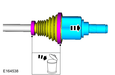
Remove and discard the large and small CV boot clamps.
-
Position the CV joint boot and the remove the inner CV joint housing.
-
Remove and discard the large and small CV boot clamps.
 |
-
-
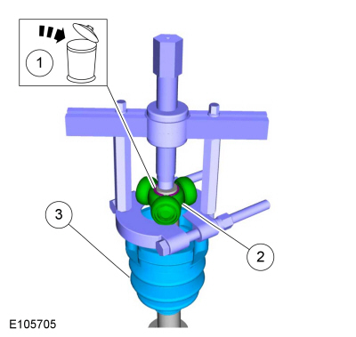
Remove and discard the CV joint tripod bearing circlip.
-
Using the bearing seperator and bearing puller remove the CV tripod.
Use the General Equipment: Puller
Use the General Equipment: Bearing Separator
-
Remove the inner CV joint boot.
-
Remove and discard the CV joint tripod bearing circlip.
 |
Installation
-
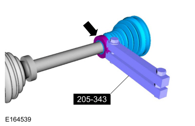
Using boot clamp pliers, install the small CV boot clamp and the inner CV joint boot.
Use Special Service Tool: 205-343 (T95P-3514-A) Installer, Constant Velocity Joint Boot Clamp.
 |
-
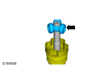
NOTE: Make sure that a new component is installed.
Using a vise, install the CV joint tripod bearing.
Use the General Equipment: Vise
 |
-
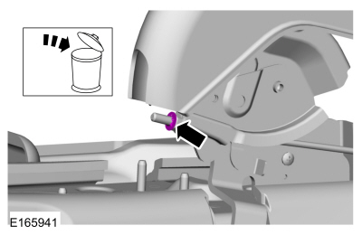
NOTE: Grease sachet is supplied with boot kit.
-
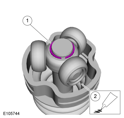
Install the new CV joint tripod bearing circlip.
-
Install the grease sachet evenly in the CV joint case.
Material: Motorcraft® Constant Velocity Joint Grease / XG-5 (WSS-M1C258-A1)
-
Install the new CV joint tripod bearing circlip.
 |
-
-
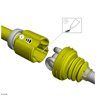
Install the grease sachet evenly in the CV joint boot and the CV joint housing.
Material: Motorcraft® Constant Velocity Joint Grease / XG-5 (WSS-M1C258-A1)
-
Position the CV joint boot and the CV joint housing.
-
Install the grease sachet evenly in the CV joint boot and the CV joint housing.
 |
-
-
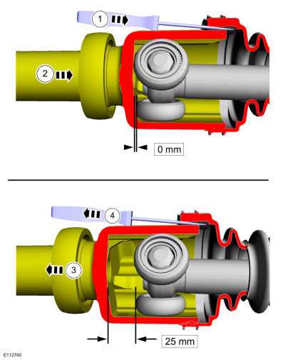
Insert the intemediate shaft into the CV boot. Use a flat blade screw driver to release trapped air.
Use the General Equipment: Flat Headed Screw Driver
-
Completely slide the intermediate shaft into the CV tripod housing until it bottoms out.
-
Slide the intermediate shaft out 25mm (1 inch).
-
Remove the flat blade screw driver.
Use the General Equipment: Flat Headed Screw Driver
-
Insert the intemediate shaft into the CV boot. Use a flat blade screw driver to release trapped air.
 |
-
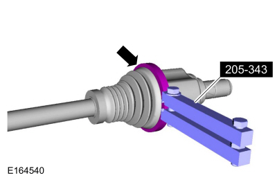
Using the special tool, position back the CV boot and install the new large halfshaft boot clamp.
Use Special Service Tool: 205-343 (T95P-3514-A) Installer, Constant Velocity Joint Boot Clamp.
 |
-
Install the front halfshaft.
Refer to: Front Halfshaft LH (205-04 Front Drive Halfshafts, Removal and Installation).
Refer to: Front Halfshaft RH (205-04 Front Drive Halfshafts, Removal and Installation).
 Front Halfshaft RH. Removal and Installation
Special Tool(s) /
General Equipment
204-161
(T97P-1175-A)
Installer, HalfshaftTKIT-1997-LM2TKIT-1997-F/FM2TKIT-1997-FLM2
205-D070
(D93P-1175-B)
Remover, Front Wheel Hub
Removal
NOTICE:
Suspension fasteners are critical parts because they affect
performance of vital components and systems and their failure may result
in major service expense...
 Outer Constant Velocity (CV) Joint Boot. Removal and Installation
Special Tool(s) /
General Equipment
205-343
(T95P-3514-A)
Installer, Constant Velocity Joint Boot ClampTKIT-1995-FTKIT-1995-FM/FLMTKIT-1995-LM/M
Materials
Name
Specification
Motorcraft® Constant Velocity Joint GreaseXG-5
WSS-M1C258-A1
Removal
Remove the inner CV joint boot...
Other information:
Ford Fiesta 2014 - 2019 Service Manual: Input Shaft Seal. Removal and Installation
Special Tool(s) / General Equipment 308-847Installer, Inputshaft Seal Center Punch Adhesive Tape Removal Remove the transmission. Refer to: Transmission (308-03B Manual Transmission - 6-Speed Manual Transmission – B6, Removal)...
Ford Fiesta 2014 - 2019 Service Manual: Side Curtain Airbag - Vehicles With: Side Curtain Airbag With Rollover Protection. Removal and Installation
Removal WARNING: The following procedure prescribes critical repair steps required for correct restraint system operation during a crash. Follow all notes and steps carefully. Failure to follow step instructions may result in incorrect operation of the restraint system and increases the risk of serious personal injury or death in a crash...
Categories
- Manuals Home
- Ford Fiesta Service Manual (2014 - 2019)
- Engine Cooling - 1.6L EcoBoost (132kW/180PS) – Sigma
- Front Suspension
- Engine - 1.6L EcoBoost (132kW/180PS) – Sigma
- Clutch - 6-Speed Manual Transmission – B6
- Lower Arm. Removal and Installation
Parking Brake Control. Removal and Installation
Removal
NOTE: Removal steps in this procedure may contain installation details.
Remove the floor console.Refer to: Floor Console (501-12 Instrument Panel and Console, Removal and Installation).
Remove the driver seat.
Refer to: Front Seat (501-10 Seating, Removal and Installation).
Remove the parking brake cable adjustment lock nut.
 Loosen the parking brake cable adjustment nut.
Copyright © 2026 www.fofiesta7.com