Ford Fiesta: Manual Transmission - 6-Speed Manual Transmission – B6 / Input Shaft Seal. Removal and Installation
Ford Fiesta 2014 - 2019 Service Manual / Manual Transmission, Clutch, Transfer Case and Power Transfer Unit / Manual Transmission - 6-Speed Manual Transmission – B6 / Input Shaft Seal. Removal and Installation
Special Tool(s) / General Equipment
 |
308-847 Installer, Inputshaft Seal |
| Center Punch | |
| Adhesive Tape | |
Removal
-
Remove the transmission.
Refer to: Transmission (308-03B Manual Transmission - 6-Speed Manual Transmission – B6, Removal).
-
Remove the bolts and the slave cylinder.
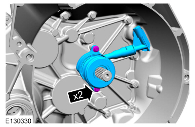 |
-
NOTICE: Take extra care not to damage the bearing.
Using a punch, poke a hole in the input shaft seal.
Use the General Equipment: Center Punch
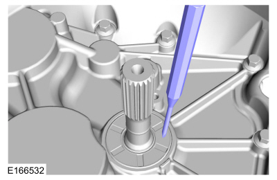 |
-
-
2.5 x 15 mm self-tapping screw
Using a 2.5 x 15 mm self-tapping screw, thread a 2.5 x 15 mm self tapping screw into the input shaft seal 2 complete turns.
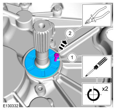
-
Using a pair of pliers, pull on the screw and remove the seal.
-
2.5 x 15 mm self-tapping screw
 |
Installation
-
-
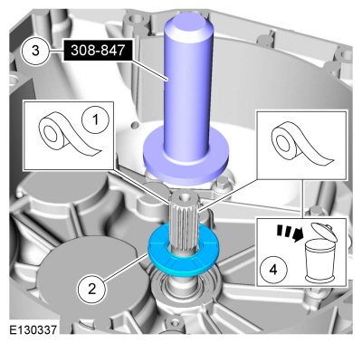
NOTICE: Use adhesive tape to cover the input shaft splines to prevent damage to the input shaft seal.
Apply tape to the splines to protect the seal.
Use the General Equipment: Adhesive Tape
-
NOTE: Make sure that a new component is installed.
Position a new seal on the input shaft in the clutch housing.
-
Using the special tool, install the seal.
Use Special Service Tool: 308-847 Installer, Inputshaft Seal.
-
Remove and discard the tape.
-
 |
-
Install the clutch slave cylinder and tighten the bolts.
Torque: 89 lb.in (10 Nm)
|
-
Install the transmission.
Refer to: Transmission (308-03B Manual Transmission - 6-Speed Manual Transmission – B6, Installation).
 Halfshaft Seal RH. Removal and Installation
Special Tool(s) /
General Equipment
308-880Installer, Driveshaft Seal
Removal
Remove the wheel and tire.
Refer to: Wheel and Tire (204-04A Wheels and Tires, Removal and Installation)...
 Selector Mechanism. Removal and Installation
Materials
Name
Specification
Motorcraft® Dual Clutch Transmission FluidXT-11-QDC
WSS-M2C200-D2
Removal
Remove the battery tray...
Other information:
Ford Fiesta 2014 - 2019 Service Manual: Brake Caliper. Removal and Installation
Removal NOTE: Removal steps in this procedure may contain installation details. Remove the wheel and tire. Refer to: Wheel and Tire (204-04A Wheels and Tires, Removal and Installation). NOTICE: If the fluid is spilled on the paintwork, the affected area must be immediately washed down with cold water...
Ford Fiesta 2014 - 2019 Service Manual: Cylinder Head. Disassembly and Assembly of Subassemblies
Special Tool(s) / General Equipment 303-1249Valve Spring CompressorTKIT-2006UF-FLMTKIT-2006UF-ROW 303-300 (T87C-6565-A) Set, Valve Spring CompressorTKIT-1988-FESTIVAT88C-1000-STTKIT-1988-TRACERTKIT-2009TC-F 303-350 (T89P-6565-A) Compressor, Valve SpringTKIT-1990-LMHTKIT-1989-FTKIT-1989-FMTKIT-1989-FLM 303-472 (T94P-6565-AH) Adapter, Valve Sp..
Categories
- Manuals Home
- Ford Fiesta Service Manual (2014 - 2019)
- Engine
- Clutch - 6-Speed Manual Transmission – B6
- Front Suspension
- Camshafts. Removal and Installation
- Lower Arm. Removal and Installation
Rear Wheel Speed Sensor. Removal and Installation
Removal
NOTE: Removal steps in this procedure may contain installation details.
Remove the retainer and pull the rear splash shield outward.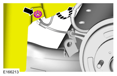 Disconnect the electrical connector and detach the wiring retainer.
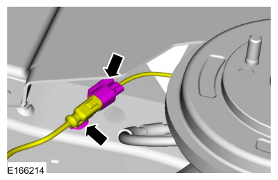
Copyright © 2026 www.fofiesta7.com