Ford Fiesta: Steering Wheel and Column Electrical Components / Ignition Lock Cylinder Housing. Removal and Installation
Ford Fiesta 2014 - 2019 Service Manual / Steering System / Steering Wheel and Column Electrical Components / Ignition Lock Cylinder Housing. Removal and Installation
Special Tool(s) / General Equipment
| Grinder |
Removal
NOTE: Removal steps in this procedure may contain installation details.
-
Remove the steering wheel.
Refer to: Steering Wheel (211-04 Steering Column, Removal and Installation).
-
Remove the PATS transceiver.
Refer to: Passive Anti-Theft System (PATS) Transceiver (419-01B Passive Anti-Theft System (PATS) - Vehicles Without: Keyless Entry and Push Button Start, Removal and Installation).
Refer to: Passive Anti-Theft System (PATS) Transceiver (419-01C Passive Anti-Theft System (PATS) - Vehicles With: Keyless Entry and Push Button Start, Removal and Installation).
-
If equipped remove the ignition lock cylinder.
Refer to: Ignition Lock Cylinder (501-14 Handles, Locks, Latches and Entry Systems, Removal and Installation).
-
If equipped remove the ignition switch.
Refer to: Ignition Switch - Vehicles Without: Keyless Entry and Push
Button Start (211-05 Steering Wheel and Column Electrical Components,
Removal and Installation).
-
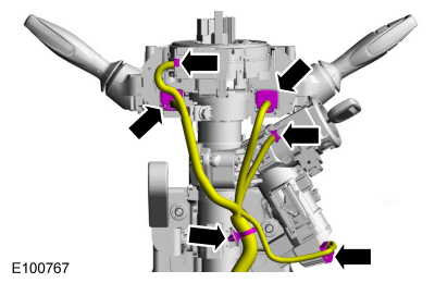
Detatch the retainer and disconnect the electrical connectors.
 |
-
-
Remove the bolt.
Torque: 71 lb.in (8 Nm)
-
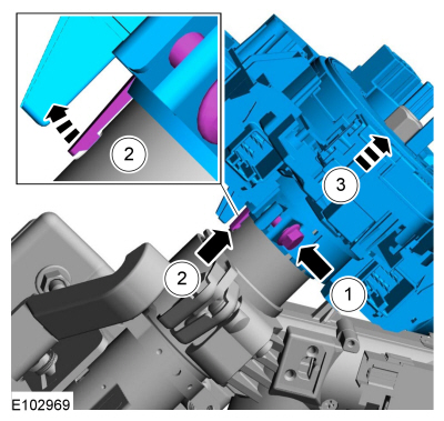
Release the tab.
-
Remove the steering column switch carrier.
-
Remove the bolt.
 |
-
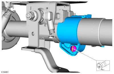
NOTE: Clean all metal shavings and foreign material after cutting a slot into the ignition lock cylinder housing bolt.
Cut a slot into the ignition lock cylinder housing bolt.
Use the General Equipment: Grinder
 |
-
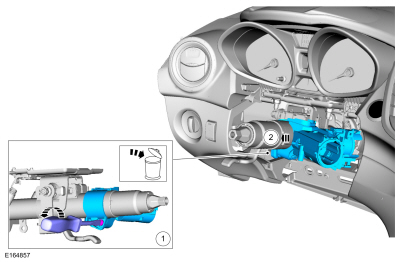
Remove the bolt and the ignition lock cylinder housing.
 |
Installation
-
To install, reverse the removal procedure.
 Steering Wheel Multifunction Switch. Removal and Installation
Removal
NOTE:
Removal steps in this procedure may contain installation details.
Refer to: Driver Airbag (501-20B Supplemental Restraint System, Removal and Installation)...
 Engine
..
Other information:
Ford Fiesta 2014 - 2019 Service Manual: Tire Pressure Monitoring System (TPMS) Sensor Activation. General Procedures
Special Tool(s) / General Equipment 204-D081A (204-D081) Tire Pressure Monitor (TPMS) Activation NOTE: The tire pressure sensors will go into a "sleep mode" when a vehicle is stationary to conserve battery power. The sensors do not transmit information while in sleep mode. It will be necessary to wake them up so they will transmit the latest tire press..
Ford Fiesta 2014 - 2019 Service Manual: Throttle Body. Removal and Installation
Removal NOTE: Removal steps in this procedure may contain installation details. Refer to: Jacking and Lifting - Overview (100-02 Jacking and Lifting, Description and Operation). Disconnect the quick release couplings. Refer to: Quick Release Coupling (310-00B Fuel System - General Information - 1.6L EcoBoost (132kW/180PS) – Sigma, General Pr..
Categories
- Manuals Home
- Ford Fiesta Service Manual (2014 - 2019)
- Clutch - 6-Speed Manual Transmission – B6
- Cylinder Head. Removal and Installation
- Engine. Assembly
- Lower Arm. Removal and Installation
- Engine - 1.6L EcoBoost (132kW/180PS) – Sigma
Front Strut and Spring Assembly. Removal and Installation
Removal
NOTE: Removal steps in this procedure may contain installation details.
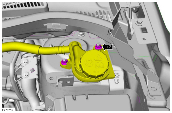
NOTE: This step is only necessary when installing a new component to the left-hand side.
Remove the nuts and position aside the remote brake fluid reservoir.Torque: 62 lb.in (7 Nm)
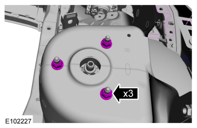
 Remove the strut and spring assembly upper mount nuts.
 Torque: 22 lb.ft (30 Nm)
Copyright © 2026 www.fofiesta7.com